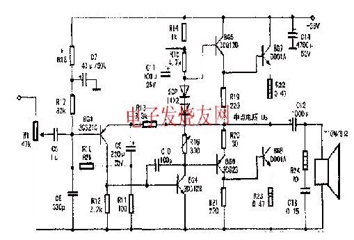
The circuit is as shown. The power amplification part of the machine is a typical quasi-complementary push-pull output circuit. BG5 and BG7 are combined into an NPN tube to form the push-pull upper arm: PNP. BG6 and NGN BG8 are combined into a PNP tube to form a push-pull lower arm. R14 and C11 form a bootstrap circuit to increase the open-loop gain and forward output amplitude of the circuit.
R15 is the load circuit of BG4. To overcome the crossover distortion characteristic of Class B amplification, a bias circuit consisting of two silicon diodes and R16 is added between the BG5 and BG6 bases, and the collector current of BG4 produces a voltage drop across them. This voltage drop is the bias voltage of BG5 and BG7, BG6 and BG8, which is about 1.8V. The voltage drop of two silicon diodes at room temperature is about 1.4V, and the rest is obtained by R16 adjustment. Since the R16 string is in the bias loop. During the process of energization and bias current regulation, R16 should start from 0Ω, and it is not allowed to suddenly increase or open the circuit. Otherwise, the bias current will be very large, and BG7 and BG8 will burn out due to the current flowing too much. R12 is the collector load resistor of BG3 and also the base bias resistor of BG4. The collector current of BG3 flows through R12 to produce a voltage drop of approximately 0.6V as the base bias of BG4. R18, R17, R10, and R11 are the bias resistors of BG3, and C7 is the bias power supply filter capacitor. R13, R11 and C9 form AC negative feedback. A part of the signal is taken out from the output terminal and added to the BG3 emitter by R13 and R11. The result of negative feedback improves the frequency characteristics and stability. Changing the resistance of R11 can change negative. The amount of feedback. Adjust the circuit gain. C12 is the output coupling capacitor, and R24 and C13 form the speaker impedance compensation circuit. Used to offset the inductive component of the speaker. The load of the amplifier is closer to the pure resistance, so that the amplifier works stably, it is not easy to generate self-oscillation, and the output stage transistor can work safely. R19 is the BG5 emitter negative feedback resistor. It is also the bias resistor of BG7; R20 is the BG6 emitter negative feedback resistor; R21 is the BG6 collector load resistor and also the BG8 base bias resistor; R22 and R23 are the current negative feedback resistors of BG7 and BG8 respectively. Normally, the current of the BG7 collector is adjusted to about 10 mA, and the power amplifier tube DD01A can be replaced by C2073.
Magnetic Hold Relay,Magnetic Relay Pcb Type,Relay Magnetic 120A 220V,Double Coil Magnetic Hold Relay
Ningbo Xingchuangzhi Electric Appliance Co.,Ltd. , https://www.xingchuangzhi.com