When using the LPUART of the STM32L496 Nucleo board for printout, there is always no information on the computer side.
According to the development board user manual, the TX/RX pin [PG7/PG8] of the peripheral LPUART is connected to the VCP port of the STLINK part of the development board by default. This has the advantage of eliminating the trouble of the flying line and eliminating the need for an external USB. - UART conversion device.

The customer's LPUART related code is modified based on the Cube library routine of the Nucleo board.
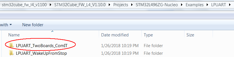
PB10/PB11 for the communication port in the above CUBE library LPUART routine. From the chip data sheet, we can know that the LPUART communication port can be multiplexed to multiple ports, such as: PA2, PA3/PB11, PB10/PC1, PC0/PG7, PG8.
Firstly, based on the routine configuration, the PB10/PB11 communication port is used for print output, and the flywheel is connected to the VCP interface of the STLINK end of the Nucleo board of the STM32L496, and the output is normal. The installation of the VCP port, the LPUART peripheral, and the PC-side vcp driver on the STLINK side is normal.
Modify the LPUART communication port to modify PG7, PG8, and do the related multiplexing function, GPIO configuration modification, the computer can not see any printing information. Even if you use the oscilloscope to directly test the LPUART output pin PG7, there is no movement. Is there anything special about PG7 and PG8? View the manual!
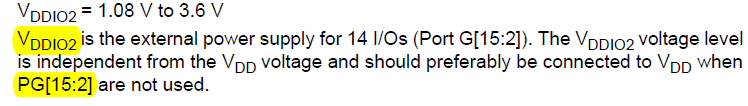
As you can see from the manual, the power supply for port PG[15:2] is handled by VDDIO2. It is now required, and the VDDIO2 pin should be connected to the relevant power supply.
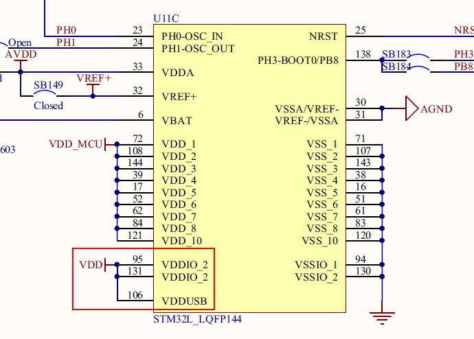
By looking at the NUCLEO board schematic, VDDIO2 is already connected to VDD.
What configuration does the software need to add? Because the VDDIO2 domain is to be operated, the power interface clock is enabled. In addition, a register bit [IOSV] that is active with VDDIO2 is asserted to indicate that the VDDIO2 domain is operational.
HAL_PWREx_EnableVddIO2(); //IOSV@PWR_CR2 ......1
__HAL_RCC_PWR_CLK_ENABLE(); //PWREN@RCC_APB1ENR1...2
Insert the first sentence code above into the HAL_UART_MspInit() function in the routine, and the second code
Add to SystemClock_Config(). Then compile and debug, the output is normal, and the problem is basically the same.
The above is based on the existing Cube library code. If you use the STM32CubeMx tool to configure it will be much faster, the STM32CubeMx code added above will help you configure it, saving you the details of the study, a lot higher efficiency. Some people may say that this efficiency comes at the expense of the grasp of the details, and there is nothing wrong with it. However, most of the time, as an application engineer, the focus is on the implementation and optimization of application functions.
Finally, by the way, I would like to remind you about the baud rate configuration of the LPUART.
In fact, in the previous test process, I also encountered some problems when setting the baud rate. The baud rate setting in the routine is 115200. When the baud rate is set to a lower value, such as 9600, it is found that the UART communication is not working. When the baud rate is increased, the work is normal again. This repeatedly verifies that the phenomenon is still the same. It should be the baud rate setting. Some details need to be further confirmed. Open the STM32L4 Reference Manual RM0394 to read the relevant chapters. The baud rate setting and parameter limits are clearly described.
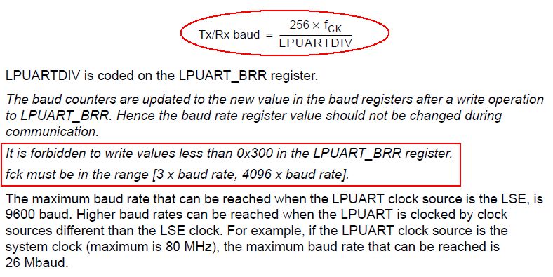
1. For the LPUART baud rate setting, in addition to the above formula, the LPUART clock must be in the range of [3 baud to 4096 baud]. During the previous test, the LPUART clock source was derived from the system clock, up to 80MHz. According to the above regulations and formulas, its baud rate should be at least 80M/4096=19531, so when we set the baud rate to 9600, we can't communicate normally. In this case, it is recommended to be more than 38400.
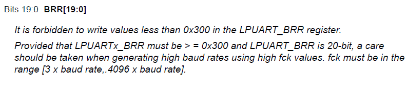
2. The clock source of the LPUART can be the system clock or the LSE. If it is 32768 LSE, according to the above regulations, the value of LPUART_BRR must not be less than 0X300, that is, decimal 768. Then the corresponding baud rate configuration should not be higher than 9600.
OK, throwing bricks and jade to share these small details, I hope to win.
Blue light filter-using blue light filter technology can eliminate blue light on the phone screen, thereby reducing eye fatigue and fatigue. And keep your eyes healthy and avoid staring at the screen.
Ultra-transparent and protective Ultra-high-quality Ultra HD provides you with clear viewing effects. Let you fully enjoy the super retina display of the screen.
Evacuation Waterproof and Waterproof-The hydrophobic and loose oil transparent layer is used as the final coating to protect screen fingerprints, liquid residues and other stains, keeping your phone in its original condition all day long.
The 0.14mm high-sensitivity touch Ultra-Thin Protective Film can provide real touch and high sensitivity, ensuring that the original high-response touch is not disturbed.
If you want to know more about Anti-Blue Light Screen Protector products, please click the product details to view the parameters, models, pictures, prices and other information about Anti-Blue Light Screen Protector.
Whether you are a group or an individual, we will try our best to provide you with accurate and comprehensive information about the Anti-Blue Light Screen Protector!
Anti-blue Screen Protector, Anti-blue Light Protective Film, Anti-blue Light Screen Protector,Anti Blue Light Screen Protector,Blue Light Blocking Screen Protector
Shenzhen Jianjiantong Technology Co., Ltd. , https://www.jjthydrogelprotector.com