Abstract : In order to meet the ever-increasing requirements of power system for relay protection devices, this paper introduces a power system capacitor protection device. The main method is to convert the collected analog signals into digital signals and compare the data according to specific logic algorithms. The comparison process is performed, and the control information is output through the logic plug-in with the relay installed to complete the corresponding protection action. In this paper, the hardware structure, function realization, motion logic and digital-to-analog conversion of the capacitor protection device are studied in detail, and the development and function of the device system are explained.
Key words: relay protection; transformer protection; measurement and control; digital-to-analog conversion; capacitor
In order to ensure the safe operation of the power system, various protection devices are widely used in system protection. As the overall structure and operation mode complexity of the power system continue to increase, the requirements for power system relay electrical protection devices are also increasing. The original analog relay protection can no longer meet the requirements of the new relay protection device in terms of testing methods and performance. The relay protection device based on microcomputer has developed its main protection functions in the direction of multi-function, intelligence, visualization and networking, including three-stage overcurrent protection, three-stage zero-sequence current protection, overload protection and overvoltage protection. , loss of voltage protection, unbalanced voltage / current protection, fault recording and small current ground selection function, this article will introduce the logic implementation of several typical functions.
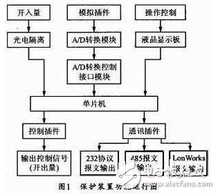
The main principle of the relay protection device developed in this paper is: the analog plug-in is responsible for collecting AC data from the power system, and converting the collected large voltage and large current signals into corresponding small voltage signals through the converter, and the small voltage signal at this time To simulate an AC signal, the analog-to-digital converter acquires these analog AC voltage signals and converts them into digital signals. The CPU main chip periodically reads the semaphores from the analog-to-digital conversion chip by interrupt mode, and these digital signals are converted into binary data that can be used by the program by Fourier transform in the program. The program compares the resulting data with the original settings according to certain logic. Therefore, it is judged whether an action is required, and if necessary, the logic plug-in is communicated, and the control of the power system is controlled by the control of the small relay on the logic plug-in, and the circuit breaker and the like in the power system are controlled to be correspondingly protected. The main function of the protection device is shown in Figure 1.

Ring And Fork Type Insulated Terminals
Ring And Fork Type Insulated Terminals,High quality insulated terminal,copper tube terminal
Taixing Longyi Terminals Co.,Ltd. , https://www.longyicopperterminals.com