Many communication systems will develop to a certain degree of miniaturization. On the one hand, miniaturization can make the system lighter and more efficient. On the other hand, the growing IC manufacturing technology can produce large quantities of small products at a lower cost.
MEMS (Micro Electromechanical System) is one of the related technologies of this small product. MEMS can detect changes in the environment and generate relevant reactions through microcircuits. The main part of MEMS includes sensor (micro-sensor) or actuator (micro-actuator) and transducer (converter), where sensor can detect the presence or intensity of a certain physical, chemical or biological, such as temperature, pressure, sound or chemical composition, The transducer converts one kind of energy into another (such as from electrical signals to mechanical waves).
At present, MEMS is widely used in many fields, as shown below.
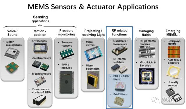
This article mainly talks about several RF related application products of MEMS such as SAW, BAW, and FBAR filter, and is also the most commonly used filter in mobile phones.
In SAW, BAW and FBAR, A represents Acoustic. Acoustic wave Chinese translation into sound waves, sound waves are divided into three segments by frequency, audio, infrasonic (infrasound) and ultrasonic (ultrasonic).
Audio's frequency is 20Hz ~ 20KHz, which is the range that the human ear can hear.
Infrasonic (infrasonic) is a low frequency, 20Hz, human ears can not hear, can be used to study geographical phenomena (such as earthquakes).
Ultrasonic is from 20KHz to 109KHz and is also inaudible to the human ear.
The sound waves mentioned below are the range of ultrasound. Let's first look at the SAW filter.
Surface Acoustic Wave(SAW) filter
As the name suggests, SAW is an acoustic wave that travels along a solid surface.
A basic SAW filter consists of a piezoelectric substrate and two Interdigital Transducers (IDTs) as shown below.
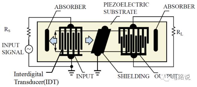
The IDT is composed of crossed metal electrodes. In the figure above, the IDT on the left transforms electrical signals into acoustic waves, and the IDT on the right converts the received sound waves back into electrical signals.
The conversion between electrical signals and acoustic waves (also referred to as mechanical waves) is also referred to as electromechanical coupling.
How does the IDT turn electrical signals into sound waves? The reason lies in the piezoelectric material below the IDT.
Piezoelectricity or piezoelectric effect
The term Piezoelectricity comes from the Greek piezein, which means exerting pressure and was discovered in 1880 by two French physicists (Pierre, Paul-Jacques Curie). Piezoelectricity refers to the fact that certain crystals (Crystal) generate voltage when they are subjected to external pressure. Conversely, if there are voltages on both sides of some crystals, the crystal shape will be slightly deformed.
Why does this happen?
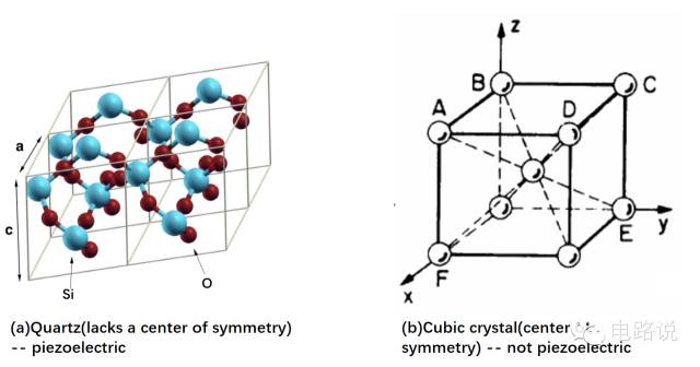
First of all, crystals are crystals. Scientific crystals refer to atoms or molecules whose atoms or molecules are arranged in a very regular manner in three-dimensional space, and solids whose unit cell is repeated at a certain distance. For example, salt and sugar are also crystals. Most of the crystals have a unit of atom symmetry (with a center of symmetry). The net electric dipole in the basic cell is always zero regardless of the external pressure. The atomic arrangement of the piezoelectric crystal is asymmetrical (lacks a Center of symmetry).
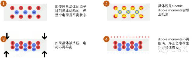
Although the arrangement of the piezoelectric crystal atoms is asymmetric, the positive charge and the nearby negative charge cancel each other out (more precisely, the electric dipole moments cancel each other out), so the whole crystal is not charged. When the crystal is stressed, the shape changes, and the distance between some atoms becomes closer or farther, disturbing the original balance, resulting in a net electrical charge, and a positive charge and a negative charge on the crystal surface. This phenomenon is called a piezoelectric effect.
On the contrary, the atoms are subjected to “electrical pressure†when a voltage is applied across the crystal. In order to maintain the charge balance, the atoms oscillate back and forth to slightly deform the shape of the piezoelectric crystal. This phenomenon is called the reverse-piezoelectric effect.
Quartz is a very common piezoelectric material, and quartz watches used in our daily life also make use of the piezoelectric properties of quartz. The button battery powers the circuit inside the watch. The circuit will allow the quartz crystal to oscillate accurately (vibration) for 32,768 times per second, and then convert the oscillation into a one-second pulse, which in turn drives the small motor and turns the gear (pointer).
The piezoelectric materials commonly used in SAW filter include LiTaO3, LiNbO3, SiO2 and so on. In its basic structure, the alternating voltage between the electrodes of the IDTs arranged on the left side produces a mechanical stress of the piezoelectric material and propagates along the surface in the form of SAW, and the SAW amplitude rapidly declines in the vertical direction. The IDT on the right is also of the same structure except that it receives SAW and outputs electrical signals. The shielding of the middle part affects the coupling between the input and the output, and relates to the amplitude ripple and the group delay in the passband.
SAW filter can also use ladder type (string and combination), as shown below.
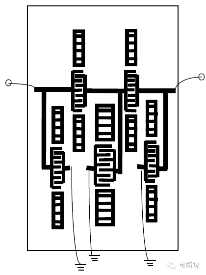
The frequency of SAW can be roughly referred to the following formula: F = V/λ
V is the SAW velocity, about 3100 m/s, and λ is the IDT electrode spacing.
It can be seen from the formula that the higher the frequency, the smaller the spacing between the IDT electrodes, so the SAW filter is not suitable for frequencies above about 2.5 GHz. In addition, too high current density (high power) at very small spacings (high frequencies) can cause problems such as electromigration and heat generation. Of course, some methods (IDT material improvements, etc.) can also compensate for these problems.
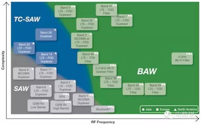
The SAW filter is also sensitive to temperature changes and performance deteriorates with increasing temperature. TC (temperature compensated)-SAW filter is to improve the temperature performance, and a protective coating is added on the IDT. The common SAW filter has a temperature coefficient of frequency (TCF) of about -45 ppm/oC and TC-SAW of about -15 to -25 ppm/oC. The added coating complicates the process and costs, but it is still relatively cheap compared to BAW filters.
Bulk Acoustic Wave(BAW) filter
BAW filter is more suitable for high frequency than SAW filter. Like the SAW/TC-SAW filter, the size of the BAW filter also decreases with increasing frequency. In addition, BAW filter is insensitive to temperature changes, low insertion loss, and steep filter skirts.
Unlike the SAW filter, sound waves propagate vertically in the BAW filter. It can also be seen from the name that SAW is the surface, which propagates along the surface, BAW is the bulk, and it propagates within the object.
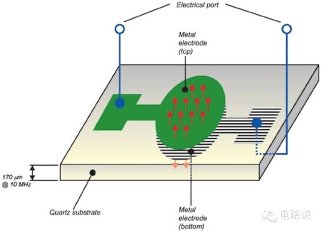
The basic structure of the BAW filter is that two metal electrodes sandwich the piezoelectric film (the thickness of the Quartz substrate is 2 um at 2 GHz), and the acoustic wave oscillates in the piezoelectric film to form a standing wave.
In order to keep the acoustic waves oscillating in the piezoelectric film, there must be sufficient isolation between the oscillating structure and the external environment to obtain the minimum loss and maximum Q value. Sound waves travel in solids at a velocity of ~5000 m/s, which means that the acoustic impedance of a solid is approximately 105 times that of air, so 99.995% of the energy of the sound wave is reflected back at the boundary between the solid and the air, as opposed to the original wave. Together form a standing wave. On the other side of the oscillating structure, the acoustic impedance of the piezoelectric material is not much different from other substrates (such as Si), so the piezoelectric layer cannot be directly deposited (deposited) on the Si substrate.
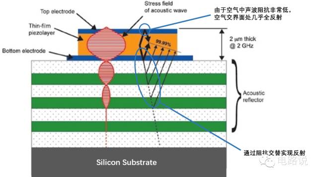
One method is to form a Bragg reflector beneath the oscillating structure and reflect the sound waves into the piezoelectric layer. The Reflector consists of several layers of alternating high-low impedance layers, such as the first layer of acoustic impedance, the second layer of acoustic impedance, the third layer of acoustic impedance, and the thickness of each layer is the sound wave λ/4, so that most of the wave It will reflect back and overlap with the original wave. The overall effect of this structure is equivalent to contact with air, most of the sound waves are reflected back, this structure is called BAW-SMR (Solidly Mounted Resonator), as shown below.
Another method is FBAR (Film Bulk Acoustic Resonator), including Membrane type and Airgap type.
The Membrane Type is etched from the back of the substrate to the surface (that is, the bottom electrode surface), forming a thin film and a cavity.
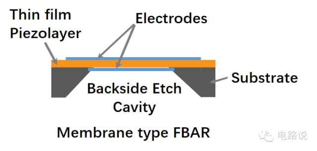
Membrane type is similar to BAW resonator's basic model, both sides are air, because the air acoustic impedance is much lower than the acoustic impedance of the piezoelectric layer, most of the sound waves will be reflected back. However, the film structure needs to be strong enough not to be affected in subsequent processes. Compared to BAW-SMR,membrane type
Less contact with the bottom substrate and less heat dissipation.
The Airgap type deposits a sacrificial support layer prior to the fabrication of the piezoelectric layer. Finally, the auxiliary layer is removed and the air gap is formed below the oscillating structure.
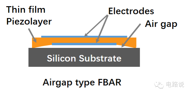
Because only the edge part is in contact with the bottom substrate, this structure is relatively weak when subjected to pressure, and similar to the mesh type, the heat dissipation problem also needs attention.
BAW filter type
BAW filter can connect multiple resonators according to a certain topology. There are several types of BAW filter, including ladder type filter, lattice type filter, stacked crystal filter and coupled resonator filter. Only the ladder type and the lattice type are briefly introduced here.
The resonators used by the Ladder type (SAW also mentioned last) include concatenation and paralleling. A concatenation of a resonator and a parallel resonator is called a stage. The entire ladder type filter can consist of several stages.

Understanding the working principle of ladder type filter Before we look at the basic model of BAW resonator, as shown below.
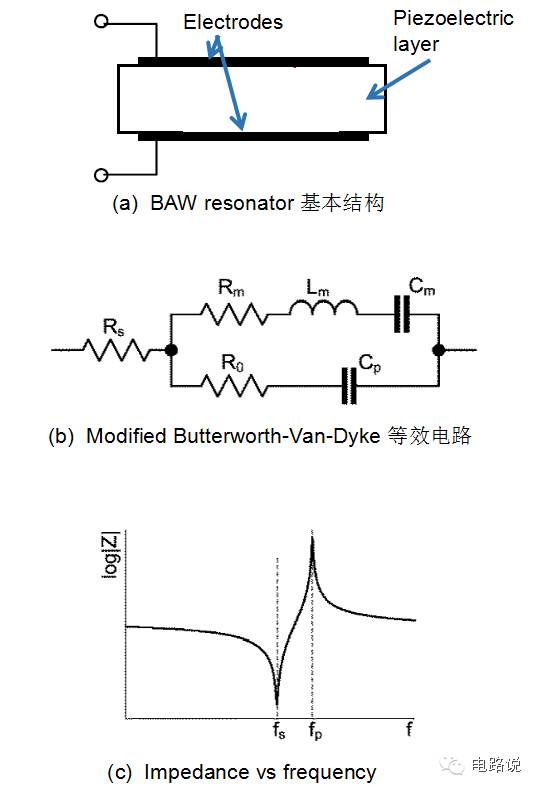
The typical basic structure is as shown in (a) above. The upper and lower metal electrodes sandwich the piezoelectric layer. The corresponding mBVD ​​equivalent circuit is shown in (b) above. The corresponding impedance is shown in (c) above. It can be seen that there are two resonant frequencies. Tandem (fs) and parallel (fp). The working principle is as shown below.
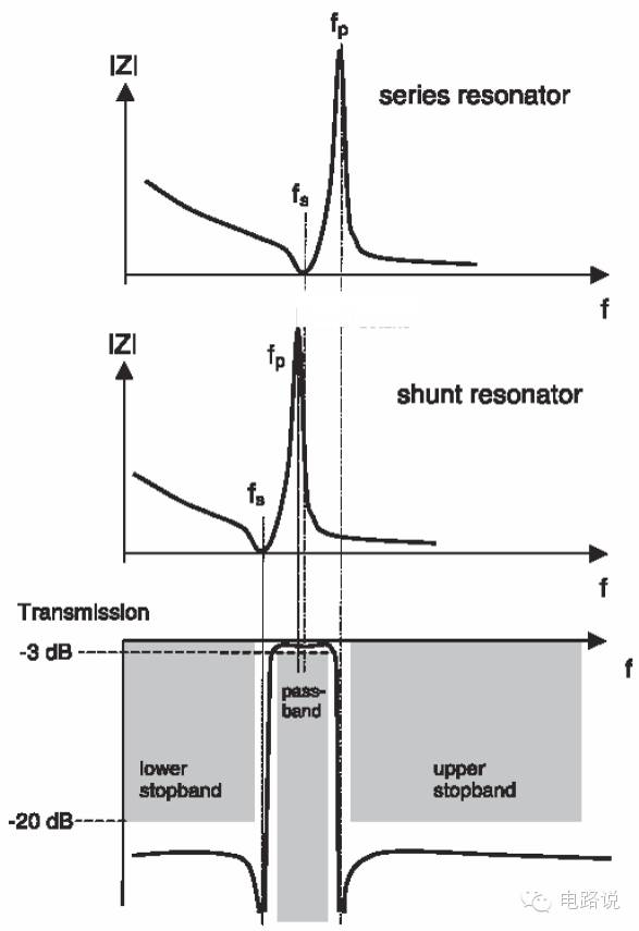
In the pass band, the series resonator fs has a small impedance, which ensures that the signal passes and the shunt resonator fp has a large impedance, preventing the signal from passing through.
Each stage in the Lattice filter has 4 resonators, including 2 series and 2 parallel connections. The basic model is shown below.
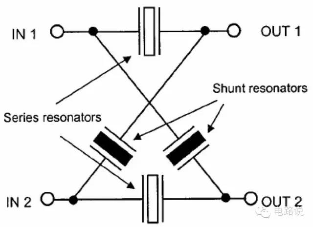
The Ladder type can be used on single-ended/unbalanced and balanced signals, and the lattice type is more suitable for use on balanced signals.
BAW filter commonly used piezoelectric materials
Quartz, as a common piezoelectric material, exhibits a linear reaction under high voltage and high pressure, but there is no suitable method for depositing quartz as a thin film on a Si substrate. Suitable BAW piezoelectric materials require high electromechanical coupling coefficient, low electromechanical loss, high thermal stability, but also conform to IC process technology.
At present, the most commonly used BAW piezoelectric materials are AlN (aluminum nitride), PZT (lead zirconate titanate), and ZnO (zinc oxide).
About wave
Physically, waves are mainly divided into two types. One is an electromagnetic wave. This wave does not require any medium but propagates through the periodic oscillation of the electric and magnetic fields generated by the first charged particles. Therefore, it is in a vacuum. Can also be spread. Radio waves, microwaves, visible light, X-rays, and gamma rays all belong to electromagnetic waves.
There is also a mechanical wave that propagates through the medium (solid, liquid, or gas) and the media's material can be deformed. For example, when sound waves propagate in the air, air molecules will collide with the surrounding molecules and continue to spread.
Mechanical waves have two basic wave motions; longitudinal (compressive) waves and transverse waves.
Longitudinal (compressive) wave (longitudinal wave)
In the P-wave, the particle's direction of motion and the wave's propagation direction are parallel, but each particle does not move along the wave's direction, but only vibrates back and forth in its own equilibrium state, as shown in the figure below.
Transverse wave
In shear waves, the direction of particle motion and the direction of wave propagation are perpendicular to each other. Particles do not move in the direction of wave propagation, but only vibrate up and down in their own equilibrium, as shown in the figure below.
In the previous BAW-SMR and FBAR filter diagrams mentioned in this article, sound waves are propagated as longitudinal waves, that is, the direction of particle vibration and the wave propagation direction are parallel. There are also different structures where sound waves propagate in the form of transverse waves.
For SAW, it is also called Rayleigh surface wave, which has both longitudinal and transverse waves. The particles in the solid oscillate in an elliptical orbit. The long axis of the ellipse is perpendicular to the solid surface. The deeper the solid, the smaller the particle motion.
REVIEW
1. MEMS is a small device or structural system, which may include integrated mechanical and electronic devices that sense timely or local environmental changes; or have some kind of physics for a timely or local environment when there is a corresponding signal input On the interaction.
2. Certain crystals (Crystal) produce a net charge when subjected to external pressure, called the piezoelectric effect; conversely, when the voltage is applied across the crystal, the atoms are subjected to “electrical pressure.†In order to maintain the charge balance, the atoms vibrate to make piezoelectric The shape of the crystal is slightly deformed. This phenomenon is called the reverse-piezoelectric effect. Quartz is a common piezoelectric crystal.
3. SAW is a sound wave that travels along a solid surface. The basic structure of SAW filter is composed of IDT and piezoelectric materials. IDT and piezoelectric materials convert electrical signals into mechanical waves (sound waves), and then convert mechanical waves (sound waves) into electrical signals. TC-SAW is to increase the temperature performance and increase the protective coating.
4. Acoustic waves propagate within the BAW filter object (longitudinal or transverse waves) compared to the SAW filter. BAW filter structure BAW - SMR, FBAR (membrane type and airgap type).
The BAW filter is more suitable for frequencies above 2.5 GHz. The BAW filter manufacturing process is also very much in line with the existing IC manufacturing process and is suitable for integration with other active circuits.
SDEC 201-400KW Diesel Generator
Sdec 201-400Kw Diesel Generato,Sdec 320Kw Diesel Genset,Sdec 350Kw Diesel Genset,Sdec 250Kw Diesel Genset
Shanghai Kosta Electric Co., Ltd. , https://www.ksdgenerator.com