In the existing front-end double wiper system, the synchronization between the left and right wipers is achieved by mechanical connection (Fig. 1). This is necessary because the dirt on the windshield, the influence of the wind, or the condition of the wiper can cause the left and right wipers to behave differently. For many years, the automotive industry has been looking for an intelligent solution that can effectively reduce noise and reduce mechanical connection space.
This article refers to the address: http://

One option is to replace the mechanical connection with an electronic system (Figure 2). In this architecture, each wiper is driven by a DC motor. The DC motor is controlled by a microcontroller and driver IC that can be mounted directly inside the motor assembly. An interface is used to handle the synchronization of the left and right wipers, so that no mechanical connections on the traditional wiper system are required between the wipers, which significantly reduces noise and saves space.

For reasons of cost, DC motors are used in the wiper system. Full H-bridge gate drivers that support PWM and four power MOSFET control direction drives can control such motors. ICs for this type of application must be designed with a high voltage process and must be suitable for use in demanding environments. In addition, high-capacity DC motor applications such as windshield wiper systems must use an optimized communication interface.
Since the electronic devices of the wiper are usually close to the vehicle radio, the EMC radiation must be controlled and the electrical signal interruption of the vehicle radio can be unbearable for the driver of the vehicle. Differential serial communication interface (SCI) transceivers can be used to reduce this type of radiation and improve EMC performance. The SCI transceiver is a differential device that operates in single-ended mode in systems with only one wiper. The SCI function of the gate driver makes it very similar to a LIN device. However, compared to the standard LIN interface, its data transfer rate is faster, up to 100k baud.
Each wiper module (Figure 3) consists of a microcontroller, a highly integrated gate driver and a DC motor. The position of the two wipers is measured by a plurality of Hall sensors. The drive passes commands to the microcontroller via the wiper switch. The electronics can be mounted close to the wiper motor, eliminating the need for a lot of space.

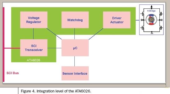
The importance of low ECU current consumption is becoming increasingly prominent. To ensure that the quiescent current of the unactivated IC is low, dedicated wake-up and sleep modes are required. The typical functional division of the wiper application is shown in Figure 4, consisting of a microcontroller, a voltage regulator that powers the microcontroller, and other discrete components such as Hall sensors. For safety reasons, a watchdog needs to be added to the system because damage to the wiper can cause danger when driving in the rain.

To further prevent system failure, ICs used in automobiles need to have many functions, such as overheat shutdown, overvoltage and undervoltage protection, and short-circuit protection, as well as strict vehicle certification requirements (radiation prevention, EMC, and ESD protection). ). To address these issues and meet the above functional requirements, Atmel has developed a highly integrated gate driver IC ATA6026. This gate driver IC includes a 5V/100mA voltage regulator plus a watchdog, which reduces the number of external components required for small designs that require a small PCB area, which is critical in electromechanical systems. This IC enables motion control, so this feature eliminates the need to add any memory to the microcontroller. The window watchdog is triggered by the microcontroller switching from low to high through the WD pin while the window is open. If the watchdog detects a window error, that is, it does not trigger when the window is open or an error is triggered when the window is closed, a reset pulse will be generated.
The block diagram in Figure 5 gives a schematic of the implemented functions and typical applications. The microcontroller controls the driving function of the IC by providing a PWM speed signal and a direction signal. Since the chip must drive the gate of the external H-bridge, it uses two push-pull drivers to control the two external power NMOS FETs used as high-side drivers, and the other two push-pull drivers are used for control purposes. Two external power NMOS FETs for the low side driver. The driver can be used with standard or logic level power NMOS FETs. The high-side control driver uses an external bootstrap capacitor to provide a voltage higher than the battery voltage of 8V to 14V. Reverse control motors are also possible. By using a charge pump to power the gate of the high-side driver, it is possible to achieve a 100% duty cycle in both directions. To prevent high peak currents in the H-bridge, switching of external power NMOS transistors is achieved using non-overlapping phases. The cross conduction time is defined by an external RC combination circuit.

Low-power and low-dropout on-chip voltage regulators are used for internal and external voltage sources. An external transistor as a power component helps to reduce power consumption. In the inactive state, the device's sleep mode ensures very low quiescent current (typically 35 microamps). For the battery voltage of 6~9V, the adjusted output voltage is 5V±10%; when the battery voltage exceeds 9V, the adjusted output voltage is 5V±3%. To prevent damage to external NPN tubes and ICs, a sense resistor can be used to sense the voltage regulator output current. If an overcurrent occurs, the voltage regulator limits the current to a specific value. This means that if the function of the voltage regulator changes to the function of the current regulator, the output voltage will drop to a very low value. If a permanent conduction state (100% PWM, no bootstrap is provided), the fully integrated charge pump can still power the gate of the high-side driver's external power MOSFET. In addition, the gate of the external power NMOS for reverse battery protection can be powered by the charge pump output.
As mentioned earlier, ECU applications require a sleep function to meet low current consumption requirements. In the sleep mode of the ATA6026, the pin EN or data wake-up IC can be used. Only a few modules are awake (bandgap, internal 5V voltage regulator with 100nF external DC blocking capacitor, input structure for detecting EN pin threshold, and wake-up module for SCI receiver). The default state of power-on is active mode. To achieve a transition between the two modes, three steps can be taken. In addition to activating/deactivating the EN pin, there is a second way to implement the wake-up function by using the SCI transceiver. In sleep mode, the SCI transceiver is partially activated and operates in single-ended mode. If the activation function is implemented with SCI, the EN pin can be held low without affecting the active mode.
Since the voltage regulator, motion control functions, watchdog and communication interface are all integrated on a single chip in a small QFN package, the total system cost is reduced, and in almost all motor drive applications that do not need to be adapted, the output stage is Maintains plug-and-play flexibility. Motion control is part of the IC and only the PWM speed signal and direction information must be provided by the microcontroller. Two diagnostic pins provide fail-safe functionality.
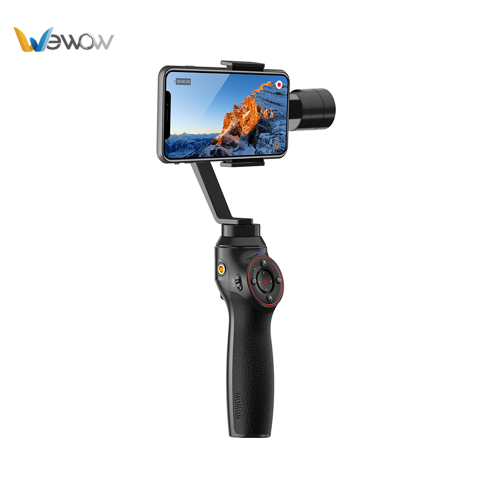
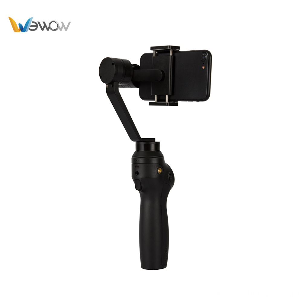
Three-axis Smartphone Stabilizer is composed of pan axis, rolling axis and tilt-axis. With a gyro-stabilized gimbal system, it keeps stabilized or steerable horizon with automatic calibration to give you an unprecedented smooth shooting experience.

Three-Axis Smartphone Stabilizer is born for video lovers. it stabilizers the video footage horizontally, without sacrificing the thrill of dynamic motion in the video.

Wewow focusing on handheld stabilizer is a technology company which does R & D independently. With Wenpod series product released, the company achieved the industry's praise and quickly became the leader of the smart stabilizer industry.
Our service
1. Reply to you within 24 hours.
2. Already sample: within 1-2days.
3. Shipping date: within 24 hours once get the payment.
4. 12 months warranty.
5. After-sales service, solve within 3 working dates.
If you have any questions, please contact with us directly.
Wewow appreciates domestic and international business relationship!
Three-axis Smartphone Stabilizer
Three-Axis Smartphone Stabilizer,3 Axis Handheld Gimbal For Smartphone,Smartphone Gimbal For Cell Phone,Three-Axis Stabilizer For Smartphone
GUANGZHOU WEWOW ELECTRONIC CO., LTD. , http://www.stabilizers.pl