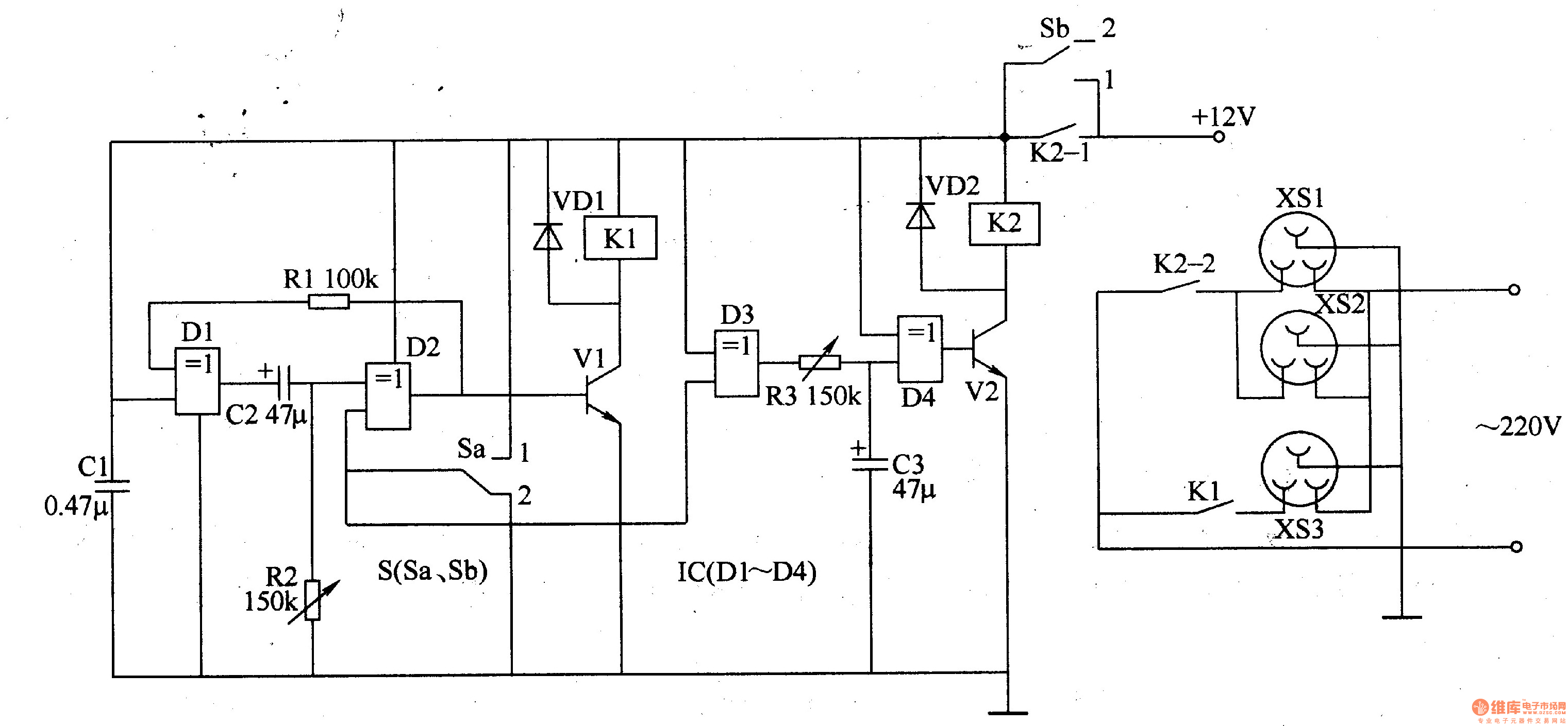
Circuit Operation Principle The computer sequentially opens and closes the socket circuit consisting of the delay control circuit A, the delay control circuit B and the voltage output circuit, as shown in Figure 3-167.

The delay control circuit A is composed of D1, D2, resistor Rl, R2, capacitor Cl, C2, power switch S (Sa, Sb), transistor Vl, diode VDl and relay Kl in the quad-OR gate integrated circuit IC (DlLD4). .
The delay control circuit B is composed of D3, D4, resistor R3, capacitor C3, transistor V2, diode VD2 and relay K2 in the IC.
The voltage output circuit is composed of a power socket XSl-XS3 and a relay Kl, and a saturated normally open contact.
When in use, the power sockets XSl and XS2 are connected to the display and the printer, respectively, and the XS3 is connected to the host computer.
When starting up, set the control contacts Sa and Sb of the power switch S to the "1" position, and the delay control circuits A and B are connected.
+l2v power supply, because the voltage at both ends of cl can not be abrupt, the monostable circuit composed of Dl, Dz, Rl, Rz and cl, cz is in a transient state, D2 output is low level, vl is cut off, Kl is not sucking, XS3 There is no output voltage, the computer host is not connected temporarily. At this time, D3 outputs a low level because both input terminals are high level, so that D4 outputs a high level, V2 saturates and conducts, K2 pulls in, which is often The open contacts Kz-l and K2-z are both turned on, the voltage output is in XS1 and XS2, and the display and printer are energized first. After a few seconds of delay (cl charging is completed), the monostable circuit enters the steady state, Dz outputs a high level, so that Vl saturates on, Kl pulls, its normally open contact Kl-l will output XS3 When the voltage is turned on, the host computer is powered on, thereby completing the functions of the peripheral device and the rear host at the time of power-on.
When shutting down, put the Sa and Sb contacts of S in the "2" position, D2 outputs the low level, so that Vl is cut off, Kl is released, its normally open contacts are disconnected, Kl is released, the voltage on XS3 disappears, the computer host The power is cut off first. At the same time, D3 outputs a high level, and charges C3 through R3. When c3 is fully charged, D4 outputs a low level, vz is turned off, K2 is released, its normally open contact is disconnected, and the voltages on XSl and XS2 disappear. The operating power of the display and printer is cut off, thus completing the functions of the first host and the rear peripheral when the power is turned off.
Component selection
Rl selects 1/4w carbon membrane resistor or metal membrane resistor for use; Rz and R3 select small organic solid variable resistors of wsw series.
Cl selects polyester capacitor or monolithic capacitor; C2 and C3 select aluminum electrolytic capacitors with a withstand voltage of 16V.
Both vDl and VD2 use 1N4007 silicon rectifier diodes.
Vl and VZ select c8oso or S80S0, 3DG80S0 type silicon NPN transistor.
Ic selects CD407o or MCl407o, cc4070 type quad-OR gate integrated circuit.
Both Kl and K2 use JRx-l3F type l2V DC relay.
S selects small bipolar double (double pole double throw) toggle switch or button self-locking switch.
The XSl-XS3 can be used with a three-prong socket on a premium combination power outlet.
When the circuit is debugged and debugged, turn on the +l2V power supply, set the Sa and Sb contacts of S to the "1" position, and adjust P2 so that Kl picks up after the contract is 3-45.
Put the Sa and Sb contacts of S in the "2" position, and then adjust R3 to release K2 after Kl release for about 3-4s.
384V 75Ah High Voltage Lithium Battery
The harsh environment and humidity have a significant impact on the telecom base station, especially for the stability of the base station. Therefore, a battery with good performance is very important to stabilize the network signal. LiFePO4 battery have a good performance in these applications. In addition, the advent of technology will drive demand for LiFePO4 batteries in telecom base stations. Notably, the development of new energy sources has brought more demand for energy storage. With the cost of lithium-ion batteries falling, LiFePO4 batteries have become a more economical investment for telecom towers with their long life, high stability, and environmental protection. This high voltage system, as an ideal backup power supply, is widely used in distributed energy, grid energy storage, photovoltaic energy storage, data room and other application scenarios that require high-voltage platform batteries.
The high voltage Lithium Battery system uses 19'' Standard Cabinet and the modular design of battery cabinets makes it useful to meet higher energy storage capacities. It can be expanded in parallel according to the need.
With centralized monitoring module and LCD Display screen, it allows users to monitor the lithium battery performance in real time, take control of battery and avoid LiFePO4 battery failure. The UFO high votage Lithium Battery system is an ideal backup power solution.
Battery Application:

Features of High Voltage DC Lithium Battery System
â— Safe LiFePO4 Battery Cells
â— 19'' Standard Cabinet Installation
â— Real-time Monitoring
â— Flexible capacity scalability
â— Wide Applicaiton
384V 75Ah High Voltage Lithium Battery,battery storage for solar, backup power ups
ShenZhen UFO Power Technology Co., Ltd. , https://www.ufobattery.com