The rotary screen printing machine is usually composed of four parts: the cloth feeding device, the printing head, the drying device, and the cloth falling device. At present, rotary screen printing machines are divided into eight-color, twelve-color, sixteen-color, twenty-four-color, etc. The circumference of the rotary screen of the rotary screen printing machine is mainly 640mm and 904mm. Among them, 640mm rotary screen printing machines are the majority. The rotary screen printing machine has the characteristics of simple operation, low labor intensity, and high output. It is suitable for printing all kinds of fabrics, and it is also suitable for printing many varieties of small batch fabrics. The main devices are introduced as follows:
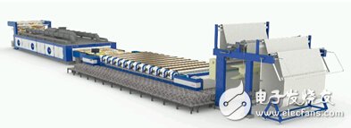
Figure 1 12-color independent transmission rotary screen printing machine
Cloth feeding device: There are two types of cloth feeding device and cloth feeding device. When the cloth is rolled into the cloth, the oscillating cloth guiding roller can be pressed on the cloth roll, and the cloth can be guided into the printing device by the rotation of the cloth guiding roller. When the cloth is fed in, the fabric will move forward with the circulating rubber guide belt to complete the printing. This guide belt is first coated with a thin layer of thermoplastic resin on the surface of the rubber roller, which can smoothly stick the fabric.
Printing device: Rotary screen printing device includes rotary screen, scraper, pulp feeding device, etc., as shown in Figure 2.
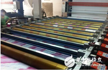
Figure 2 Printing device
The rotary screen is the pattern of the printing machine, which is made of nickel metal, also known as the nickel screen, which has a hexagonal mesh. Both ends of the rotary screen are fixed with bulkheads to prevent deformation of the rotary screen during printing, which affects the accuracy of the flower, and can withstand the pressure of the color paste and the scraper when printing. In order to improve the elasticity of the rotary screen and reduce the pressure it bears, the rotary screen should be installed off the center line of the support roller, generally about 16mm. Each cylinder frame has a reading device, which can show the pressure of the scraper in all directions.
The scraper is installed on the scraper frame on the center line of the cylinder. The scraper frame is equipped with both a scraper and a slurry pipe. The scraper is made of chromium, molybdenum, vanadium, and steel alloys, and has the characteristics of small friction coefficient and adjustable angle. When printing, the blade of the squeegee is tangent to the inner circle of the cylinder, and the squeegee applies pressure to the color paste as a combined action as the main force and scraping as a supplementary action.
The pressure and position of the scraper of the rotary screen printing machine can be adjusted to suit various patterns and fabric printing of various thick and thin color pastes.
Printing device Rotary screen printing machine is automatic slurry feeding, and each rotary screen is equipped with a slurry feeding system. When supplying color paste, put one end of the plastic tube on the machine on the metal paste supply tube, and insert the other end of the hose outside the machine into the color paste bucket, use a pump to feed the cylinder, and the electrode automatically controls the height of the color paste.
Drying and cloth placement device: Rotary screen printing machine adopts loose hot air drying. After printing, it will be separated from the rubber guide belt, led into the drying part, laid flat on the polyester net in a loose style, and dried by hot air to produce the cloth. The cloth is drawn by the electric orbiting shaft and falls into the cloth car.
The rotary screen printing machine has the advantages of low labor intensity, high production efficiency, and strong adaptability to fabrics. It is suitable for printing on chemical fiber fabrics, knitted fabrics, and light fabrics; it can obtain the effects of lively patterns and bright colors, and can avoid color transfer. Defects. However, due to the limitation of the rotary screen structure, the effect of printing fine lines is not very satisfactory. This article gives a detailed introduction to the 12-axis control of the rotary screen printing machine.
2 Principles of control system designIn this article, the rotary screen printing machine is a 12-axis printing, and the 12-axis rotary screen needs to synchronize the color registration. During the acceleration and deceleration process of the host, the 12-axis printing roller needs to follow precisely and synchronously. When the color register shifts, the axis position needs to be adjusted in real time. The main control requirements are as follows:
2.1 12-axis synchronous follow control
The printing roller needs to be synchronized with the speed of the rubber guide belt. The rubber guide belt is controlled by the frequency converter to drive the main motor through a 1/25.5 reduction box. After the following spindle is installed on the main motor, the resolution of the encoder is 1024P/R. Connect the encoder signal to the X0.8 and X0.9 terminals of AH10PM. AH10PM can carry 6 axes, so two AH10PM are needed, and the encoder signal can be connected to two AH10PM terminals. In AH10PM, the motion program of the master-slave electronic gear relationship can be established.
2.2 The net head runs alone
After printing, it is necessary to clean the guide belt and the rotary screen, and the 12 net heads need to be operated separately when the guide belt is not running. This function can make 12 mesh heads follow the virtual main axis by creating a virtual main axis in AH10PM. The virtual main axis performs JOG or variable speed motion. Because the master-slave relationship is established between the 12 axes and the virtual main axis, the 12 mesh heads will follow the virtual main axis to move. In normal production, let the virtual main axis follow the motion of the master encoder, and the virtual main axis keeps the master-slave relationship with the 12 axes all the time. In different situations, they are all synchronized.
2.3 Correction of flowers
In the printing process, due to the tension of the cloth, the friction between the guide belt and the cloth, the deformation of the cylinder, etc., the color shift will be caused. It is necessary to realign the suit color by correcting the phase between the mesh head and the conduction band. We have established the relationship of the electronic gear through the virtual main axis and 12 axes. When correction is needed, the numerator of the electronic gear can be changed in real time. Deviation correction in technology is divided into fast forward, fast backward, slow forward, and slow backward, which can be realized by setting different gear ratios.
2.4 Touch screen, analog quantity, I/O point control
The various devices of the rotary screen printing machine such as the oven, the water valve, the orbiting frequency converter, the up and down of the guide belt, the correction fast forward, fast rewind, slow forward and slow retreat buttons are all through the Delta DVP-ES2 and AH500 CPU for PLC-link communication, and then AH500 CPU exchanges data with AH10PM, reads in external signals, and changes corresponding variables to achieve control.
3 hardware architectureBuild the hardware architecture according to the above system requirements, as shown in Figure 4, Figure 5 and Figure 6.
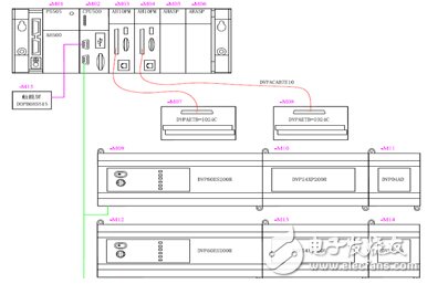
Figure 4 Hardware structure diagram
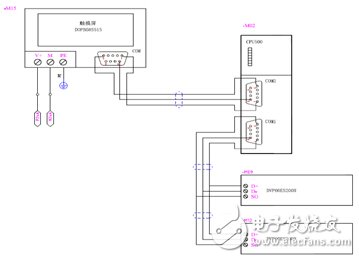
Figure 5 Hardware structure diagram
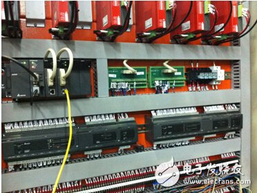
Figure 6 On-site hardware diagram
What needs attention is the interference problem of the entire electrical cabinet on the actual site. The terminal of the high-speed counter of AH10PM is collector input. The pulse output of the first four axes of AH10PM is differential, and the pulse output of the latter two axes is collector output. The collector is easily affected by external interference. It is recommended that the main encoder use push-pull output. In this way, the shielding layer should be grounded at a single end, and the entire electrical cabinet needs to be well grounded, otherwise it is easy to cause position deviation between the modules.
4 Software architectureAccording to the above system requirements, the motion program architecture can be constructed, as shown in Figure 6.
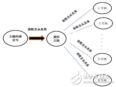
Figure 7 Motion program architecture
When the system is running normally, the virtual main shaft follows the main encoder. By changing the gear ratio between the main encoder and the virtual shaft, the friction coefficient between the guide belt and the mesh head can be adjusted on the touch screen. When the color shift occurs, the gear ratio between the virtual main shaft and the slave shaft can be adjusted to adjust the phase between the guide belt and the mesh head.
When a single-moving mesh head is required, you can directly JOG or move the virtual master axis at a variable speed, and the slave axis will also follow the virtual master axis.
5 PLC-link and AH500 backplane data exchangeIn this case, all the external I/O points are connected to the Delta DVP-ES2 small PLC, and then transferred to the AH500 CPU by the PLC-link. PLC Link is a network mechanism for data exchange through RS485 connection. Delta AH500 is a graphical planning interface, providing PLC Link and Ether Link host data exchange, convenient and fast functions, simple form filling and setting, that is, it can realize complex data exchange communication functions without programming, and is aimed at OEMs. The equipment collects information centrally to the application requirements of FMCS or ERP, which is particularly helpful.
The data between the AH500 CPU and the AH10M module is realized through backplane communication, and the mutual exchange register addresses are defined by establishing a data exchange table.
6 ProgrammingThe program is mainly divided into axis initialization, normal production of the system, that is, following the main encoder, net head single movement, net head alignment and deviation correction.
The initialization of the No. 1 axis is shown in Figure 8, and the other axes are similar. Define the highest speed, lowest speed, acceleration/deceleration time and pulse output mode of the motion axis. The highest frequency of the first four axes of AH10PM can reach 1MHz, and the highest frequency of the latter two axes is 200kHz. For the sake of unification, we set them to 200kHz.
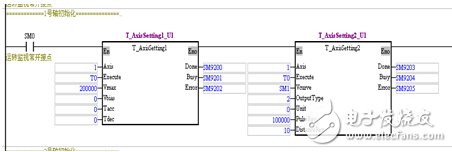
Figure 8 Initialization program for axis 1
The creation of virtual axis does not need to be initialized, it can be directly declared with axis number K7~K16. Figure 9 shows the master-slave relationship between the master encoder and the virtual main axis. The master axis is 0, that is, the high-speed counters X0.8 and X0.9. The slave axis is 7, which is the imaginary axis.

Figure 9 The program for establishing a master-slave relationship between the master encoder and the virtual main axis
The 12-axis follows the movement of the master encoder to establish a master-slave following relationship. As shown in Figure 10, the No. 1 axis follows, and the other axes are similar.

Figure 10 No. 1 axis following program
The correction function is divided into fast forward, fast backward, slow forward, and slow backward, which can be realized by changing the gear ratio, as shown in Figure 11 to establish a following condition function block.

Figure 11 Following condition function block
The cloth count length is the count length of the main encoder. This length can be cleared at any time, so the pulse value of the virtual spindle cannot be used directly. However, another virtual axis can be created for length counting, and it can be cleared at any time without affecting the normal operation of other axes, as shown in Figure 12.
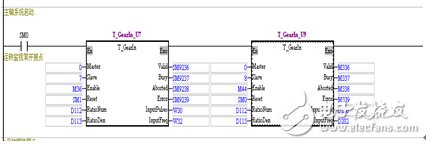
Figure 12 Length of cloth counting program
In the program, the 8th axis follows the main encoder to record the number of pulses. D200 is used as the length meter. When it needs to be cleared, it can be realized as long as M44 is disconnected for one cycle and then turned on. Pass D200 to the AH500 CPU to calculate the length.
7 concluding remarksSolutions based on Delta's medium-sized PLC AH500 and AH10PM motion modules have been successfully applied on rotary screen printing machines, and the vehicle speed can reach 100M/min. At the same time, if you choose Delta's servo drive and Delta's PLC controller to be used together, you can customize more solutions for customers, and provide customers with low-cost, high-performance, and optimized system solutions.
Lamp Holder,Bulb Holder,Light Holder,Lamp Socket
WENZHOU TENGCAI ELECTRIC CO.,LTD , https://www.tengcaielectric.com