The temperature and humidity indicators in environmental conditions are important parameters in many workplaces. Whether it is warehouse management, book preservation, or industrial measurement and metrological verification, it is necessary to meet the temperature and humidity environmental conditions of the operation regulations. Temperature and humidity are also the most difficult indicators to protect. For this situation, it is very important to develop a reliable and practical temperature and humidity monitoring system. The monitoring system is based on the RS-485 bus protocol to form a distributed network structure. The multi-machine system consisting of PC and MCU completes the measurement and control tasks.
2 system hardware structure and working principle2.1 Network Monitoring System Structure
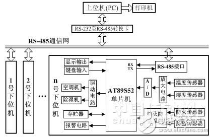
Figure 1 System structure schematic
The schematic diagram of the system structure is shown in Figure 1. The system uses a two-stage master-slave bus network topology. It consists of a PC (as the host computer), several AT89S52 microcontrollers (as the lower computer) and the RS-485 bus communication network. Under the control of the monitoring system management software, the whole system works in the same coordination to complete the design function.
2.2 master-slave communication network
The network communication in the monitoring system is connected by RS-485 serial bus. The serial communication has the characteristics of long transmission interval, simple connection, flexible use and high reliability of data transmission. It has been obtained in industrial monitoring, data acquisition and real-time control systems. widely used. The RS-485 (EIA-485 Standard) bus protocol using differential communication for signal transmission and reception improves the anti-common-mode interference capability and transmission rate compared with the RS-232C protocol, and expands the transmission interval, which is more suitable for fieldbus application. Industrial control and real-time monitoring systems in the environment [1].
The lower field data acquisition and control unit is connected to the same data communication bus, and the bus is shared by each field unit. To avoid competition and conflict of bus communication, the system network communication adopts master-slave and broadcast communication control methods. The main control microcomputer determines the start and end of a communication process, and realizes the network communication with the lower MCU and the main control microcomputer by assigning the bus communication usage right to the field unit that needs communication. When the next MCU in the network requests communication, it must wait for the host microcomputer to assign the bus usage right to it before sending and receiving data [2]. Although the master-slave communication control method is adopted, the speed is slightly slower, but since the information exchange between the field single-chip microcomputer and the main control microcomputer is not particularly frequent, it is applicable to the monitoring system.
The communication protocol used between the PC master microcomputer and each field unit microcontroller is a custom, non-standard, relatively simple format. The main control PC microcomputer sends command frame information to the bus communication protocol conversion controller through the RS-232C serial port, and the bus controller interface circuit is responsible for mutual conversion between the RS-232C level and the RS-485 level, and forwards the communication frame to the RS-232. 485 bus network broadcast. In the communication frame, the lower field unit number required by the main control microcomputer is included, and all the lower field unit MCUs listen to the broadcast. After receiving the broadcast frame, the number comparison operation is performed, and each lower-level MCU carries the received number and its own number. Comparing, the lower-level single-chip controller with the same number is the selected lower-level machine, and the received frame information is processed. The other lower-level single-chip controllers are all unselected lower-level machines, and need to discard the received frame information and continue network detection. Listen to work [3]. Similarly, when the lower field unit MCU sends an information frame to the main control microcomputer, the bus communication protocol conversion controller converts the RS-232C communication protocol level to the main control microcomputer for forwarding. In the design experiment, the monitoring system has normal communication baud rate of 9600 bit/s, no parity, 8 data bits, 1 stop bit setting, and no frame loss or frame error occurs.
2.3 lower computer data acquisition and control unit
The lower computer is a data acquisition and control unit with AT89S52 microcontroller as the core. AT89S52 is a low-power, high-performance CMOS 8-bit microcontroller. The device is manufactured by ATMEL's high-density, non-volatile memory technology. It is compatible with the standard MCS-51 command system and 80C51 pin structure. The powerful AT89S52 can be a lot of Embedded control applications provide a cost-effective solution. The AT89S52 has the following resources: 40 pins, 8k Bytes Flash on-chip program storage (In system programmable can be erased 1000 times), 256 bytes of random access data memory (RAM), 32 external bidirectional input/output ( I/O) port, 5 interrupt priority level 2 interrupt interrupt nesting interrupts, 2 16-bit programmable timing counters, 2 full-duplex serial communication ports, watchdog (WDT) circuit, on-chip clock oscillator . The power save mode can be set by software. In idle mode, the CPU suspends operation, while the RAM timer counter, serial port, and external interrupt system can continue to operate until external interrupt activation or hardware reset [4]. The lower computer is connected with 8 temperature and humidity sensors for temperature and humidity detection, and controls the dehumidifier, air conditioner or other facilities according to the uniform temperature and uniform humidity of each channel, so that the ambient temperature and humidity are controlled within a specific range. And alternately display uniform temperature and humidity values. The lower machine is also equipped with smoke, flare and pyroelectric infrared sensors and related circuits to form a fireproof and anti-theft alarm system. The lower MCU is connected to the bus network through the TTL/RS-485 communication interface circuit to form a half-duplex master-slave serial communication network, so that the lower computer exchanges data with the host computer through the serial port. The lower computer is a relatively independent intelligent area data measurement and control subsystem. When the communication between the monitoring host and the lower MCU fails, each lower computer can independently complete the data acquisition, alarm and control functions of the relevant area.
Each temperature and humidity sensor converts the detected temperature and humidity physical quantities into electrical signals, and after being amplified by respective low noise amplifiers and analog-to-digital converters (A/D), it is sent to the AT89S52 single-chip microcomputer for data analysis and processing. The lower computer can accept the access of the upper computer, and transmit the temperature and humidity data to the upper computer in real time according to the needs, and the upper temperature machine records the temperature and humidity data of each warehouse and processes it accordingly. Because different weapons and equipment have different requirements on ambient temperature and humidity, the user can set the temperature and humidity indicators of the system monitoring in the required range by adding a keyboard, so that the system can adapt to different needs.
IEEE 1394/Firewire Connector Overview
The IEEE 1394 connector series is capable of accommodating data rates up to 400 megabytes per second for serial transmission-consists of six-position connectors (for connections of computers to peripherals), and four-position connectors (for connections of digital AV equipment. We offer a screw thread size of M1.6 and two types of headers: dual inline package (DIP) and surface-mount technology (SMT). These four-position connectors help us manage a wide range of device designs and are suitable for DVD, set-top box, etc. The cable assemblies are also available with four-position to four-position type, for connection of AV equipment; four-positions to six-positions of transition type, for connections of PC and AV equipment; and six-position to six-position type for connections of PC and peripherals.
IEEE 1394 Connectors Product Features
Conforms to IEEE 1394 standard
Easy connections for plug and play devices
Available for wide range of connectors
DIP and SMT types available for PCB side
For 0.8mm and 1.6mm PC boards, M1.6 and M2.1 (4-position) panel mounting screw thread sizes
Use for automatic mounting machines with embossed tapes (4-position)
Fire Wire (IEEE 1394) Connector Wire to Borad Connectors
No of Contacts 4, 6, 9
Type
4pin IEEE 1394 Connector Female PCB Mounting Straight
4pin IEEE 1394 Connector Female PCB Mounting Right Angle
6pin IEEE 1394 Connector Female PCB Mounting Straight
6pin IEEE 1394 Connector Female PCB Mounting Right Angle
4pin IEEE 1394 Connector Male Wire Moulding type
6pin IEEE 1394 Connector Male Wire Moulding type
9pin IEEE 1394 Connector Male Wire Moulding type
9pin IEEE 1394 Connector Female PCB Mounting Right Angle
IEEE 1394 Connector With Female SMT 04P
IEEE 1394 Connector With Female SMT 09P
")
IEEE 1394 Connector Application:
IEEE1394 (Firewire) interface, IEEE1394 is a serial standard. .Like USB, IEEE1394 also support hotplug peripherals and can provide power for peripherals,
eliminating the need for built-in power supply. IEEE1394 supports multiple devices as well as synchronous data transmission.
Cameras
Camcorders
Scanners
Printers
DVD Players
Set-Top Boxes
Computer Monitors
Audio Video Receivers
Hard Drives
Audio Recording Devices
1394 Connector,Ieee 1394 Connectors,1394 Usb Connector,1394 Pcb Connector,Firewire Connector,IEEE 1394 USB Connector,1394 Firewire Connector
ShenZhen Antenk Electronics Co,Ltd , https://www.antenkwire.com