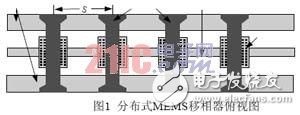
In recent years, with the development of RF micro-mechanical technology, MEMS phase shifters have attracted more and more people's attention, and have become one of the main research MEMS devices. Compared with traditional phase shifters, MEMS phase shifters mostly use semiconductor materials as substrates and are fabricated by micromachining technology. They have frequency bandwidth, low loss, low cost, ultra-small size, and easy integration with IC and MMIC circuits. Advantages, therefore, has a wide application prospect in microwave and millimeter wave control circuits [1]. Dr. Barker of the University of Michigan in the United States first implemented a millimeter-band wide-band MEMS phase shifter by periodically loading a MEMS metal bridge on a coplanar waveguide. As shown in Figure 1, its basic principle is to change the MEMS metal bridge. The height changes the phase shift constant on the transmission path to achieve the purpose of changing the phase shift [2]. This paper designs a 90° distributed MEMS phase shifter based on a capacitively coupled MEMS switch.

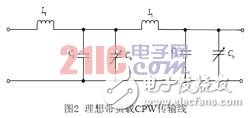
The basic design idea of ​​the distributed MEMS phase shifter is to periodically load a MEMS movable thin film bridge with a high capacitance ratio on the coplanar waveguide, thereby increasing the distributed capacitance between the coplanar waveguide and the ground, so that the coplanar waveguide transmission line becomes A slow wave system that acts as a phase delay [3]. Applying a DC bias on the line can change the distributed capacitance, causing changes in the transmission line parameters, thereby changing the phase of the electromagnetic wave. The amount of phase shift is determined by the ratio of MEMS cell capacitance (  ) and the transmission line's own capacitance is determined. The equivalent circuit diagram of the distributed MEMS phase shifter operating during phase shifting is shown in Figure 2 [4].

1 C and 1 L are the distributed capacitance and inductance of the CPW transmission line, respectively.


Then the characteristic impedance is:

The phase velocity is:


Design index: passband 34-38GHz, in-band attenuation less than 0.5dB, undulation less than 0.4dB, S(21) phase shift between 85° and 95°. The reflection loss is less than -20 dB at 36 GHz.
By applying a low dielectric constant thin insulating medium on the coplanar waveguide signal line, the MEMS metal bridge and the coplanar waveguide signal line form a MIM capacitor in an "off" state, thereby achieving an improvement of "off" and "on". The ratio of capacitances in both states increases the amount of phase shift per unit length. At the same time, the structure avoids problems because a single bridge falls short-circuit signal lines cause the failure of the phase shifter [5].

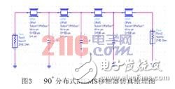
Starting from the miniaturized equivalent circuit, the simulation principle diagram of the phase shifter working at phase shift is shown in Figure 3:

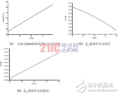
Figure 4-6 shows the simulation results calculated using ADS.

From the above three figures, it can be seen that the loss of the phase shifter is within -1dB, the reflection coefficient at the center frequency of 36GHz is less than -20dB, the insertion loss is greater than -0.042dB, the phase shift is 90° at the center frequency, and the phase shift accuracy is ±5. Within °. Moreover, such distributed MEMS phase shifters can still achieve good linearity over a wide frequency band. Optimization gives W = 19 μm, L = 134 μm, C = 25 fF.
The size of the capacitor is optimized by ADS below. by  To set the optimization objective function. We all know this formula:

From this  Value. This value is obtained to optimize the optimum value of the capacitor geometry.
The capacitance geometry calculated by ADS is: W = 0.18mm, L = 1.63mm (7)
3 ConclusionThe development of distributed MEMS phase shifters is getting faster and faster. On the basis of the traditional distributed MEMS phase shifter structure, a low dielectric constant insulating medium is applied between the coplanar waveguide signal line and the MEMS metal bridge. The method achieves a high capacitance ratio under two operating states, thereby increasing the phase shift amount per unit length. In this paper, I focus on the simplest equivalent circuit from the miniaturized equivalent circuit, and an ideal circuit model without considering the equivalent impedance of the metal. Through computer simulation, the reflection loss of the phase shifter is less than -20dB in the passband 4GHz, and the insertion loss is greater than -0.044dB. In order to achieve the phase shift of 90°, only three MEMS metal bridges are needed. This greatly reduces the overall size of the phase shifter, improve the reliability of the work.
Ningbo Xingchuangzhi Electric Appliance Co.,Ltd. , https://www.xingchuangzhi.com