With the improvement of people's living standards, the aging of our country's population is becoming more and more obvious. As a kind of service robot, vacuum cleaners can replace people in simple tasks such as cleaning rooms, workshops, and walls.
The service robot has a broad field and has become the focus of research in some enterprises and scientific research institutes. Although the current vacuum cleaners on the market are also intelligent, most of them have high costs due to unreasonable structure, poor versatility, and high integration, which is not conducive to popularization. Based on the research and summary of relatively mature products on the market, an indoor vacuum robot with self-navigation function is designed based on the ARM Cortex-M3 processor. It is compact in appearance, simple in structure, stable in operation, low in noise, low in cost, easy to operate, and has an expandable interface. Users can further develop its functions according to actual needs.
1 Overall composition of the vacuum cleanerUse the ARM Cortex-M3 processor to design a mobile cleaning robot for indoor use. The main task is to clean the room autonomously, so it should have the following functions:
(1) Able to correctly judge the room where the robot is located and its position in the room;
(2) It can correctly detect obstacles such as walls and furniture in the room;
(3) After traveling all the rooms and completing the cleaning task, they can autonomously return to the starting point and shut down.
In order to prevent the robot from blocking when it is working, and to freely enter the bottom of some furniture such as sofas, tables, etc., the vacuuming robot should not be too high and adopt a semi-cylindrical shape. The chassis is supported by four wheels, of which the left and right sides are the driving wheels, which are directly driven by two micro DC motors, and the front and rear universal wheels play the role of support and guidance. A multi-sensor system is composed of collision, infrared sensors, and ultrasonic. Infrared receiving sensors are installed on the top of the robot, and proximity sensors are evenly distributed on the edge of the chassis to detect obstacles; collision sensors are installed in the front of the robot; ultrasonic ranging sensors are installed in the front and left and right to detect the surrounding environment.
The overall frame design is shown in Figure 1.
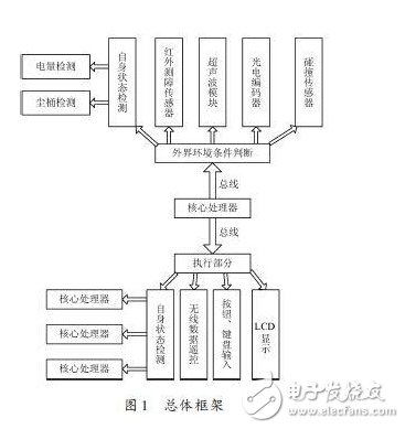
The hardware system is mainly composed of ARM Cortex-M3 processor, sensor module, motor drive module, human-computer interaction module, and wireless remote control transmitter module.
2.1 ARM Cortex-M3 processing
The main task of the robot control system is to plan the cleaning path, control the cleaning and vacuuming mechanism, and complete various control actions based on the data fed back by the sensors and encoders. Design a suitable man-machine interface to display the robot status and running time on the LCD. Therefore, the robot control system includes a sensor module, a motor drive module, an infrared remote control receiving module, an LED indicator and a liquid crystal display module. The ARM Cortex-M3 processor is used as the core of the robot control system, which is mainly low-cost, small pin count and low power consumption, and has extremely high computing power and strong interrupt response capability, and the working current is only 50 mA.
2.2 Motor Module
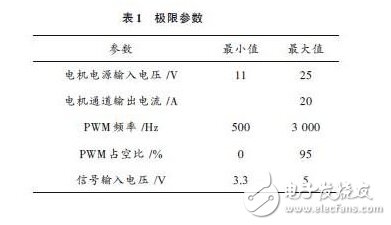
Divided into a small motor drive circuit and two high-power drive boards, including two small DC motors for walking and a high-power brushless DC motor for dust collection, a DC brush motor for sweeping the floor, and a DC side brush motor for sweeping corners . Because the motor determines the robot's walking path and dust collection power respectively, a special drive board is designed, as shown in Figure 2. The design of the walking module plays a vital role in the obstacle avoidance planning of the cleaning robot. We design the cleaning robot as a closed-loop control, which mainly includes a drive circuit and a photoelectric coding feedback circuit. The photoelectric encoder feedback circuit obtains the current motor speed by calculating the number and phase of the feedback pulses. The chip can drive a motor up to 25 V. The working voltage of the walking motor in the vacuum cleaner is 24 V, and the voltage of the chip is 5 V. The PWM wave output by the chip is transformed into a large voltage PWM wave to control the motor. The limit parameters are shown in Table 1.

2.3 Sensor module
It mainly includes 3 parts: ultrasonic module for detecting and sensing obstacles, infrared and collision sensors, and sensors for status detection (detecting battery power, dust bucket, motor stalled and suspended). The sensor module enables the robot to make correct judgments on the surrounding environment and provide intelligent decisions for the smooth completion of tasks.
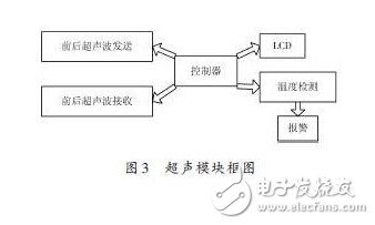
(1) Ultrasonic ranging sensor block
Indoor vacuum robots must be able to detect obstacles of various sizes, heights, and colors due to their working environment. Ultrasonic is a non-contact detection technology that is not affected by external factors such as light, smoke, and electromagnetic fields. Compared with infrared sensors, ultrasonic sensors have a longer sensing distance, high reliability, and low cost. Therefore, the use of high-precision ultrasonic ranging system can effectively complete the obstacle detection.
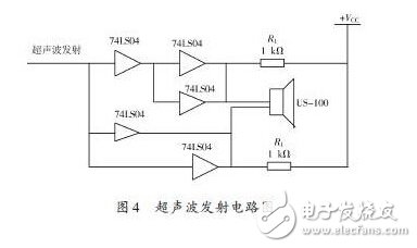
In this article, the US-100 ultrasonic ranging module can realize the non-contact ranging function of 0~4.5 m, has a wide voltage input range of 2.4~5.5 V, static power consumption is less than 2 mA, and comes with a temperature sensor to measure The distance results are corrected, and it has multiple communication methods such as GPIO and serial ports, and the work is stable and reliable. Two ultrasonic sensors are installed on the front and back of the robot. The processor generates 40 kHz pulses and outputs them through the I/O port. Then they are amplified by NAND gates and transistors to form two pulses with opposite polarities and input to the two pins of the ultrasonic transmitter. , The probe can send out a series of 40 kHz ultrasonic waves and return to the receiving circuit after encountering obstacles. The processor controls the gate circuit at the same time to realize the discontinuity of the transmitted waves. The ultrasonic receiving end uses the principle of piezoelectric conversion to convert the signal reflected by the obstacle into an electrical signal, after low-noise amplification and band-pass filtering, and then compare and generate an interrupt to the processor for time measurement, thereby making the obstacle distance judgment ,As shown in Figure 4.
(2) Infrared and collision sensor module
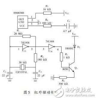
The cleaning robot mainly uses ultrasonic distance measurement for long-distance obstacles when it is working, but ultrasonic waves are not sensitive to short-distance obstacles, so an infrared module is added for short-distance detection, and an infrared measurement module is designed according to the energy reflection method. Two sets of infrared sensors are installed on the front and back of the robot, each group consists of up to 14 sets of infrared transmitting and receiving tubes, 14 on the top of the robot and 14 on the chassis, each of the upper and lower two infrared transmitting and receiving tubes are connected in parallel and point to the same direction Form a group, each group of circuits can be divided into high-frequency pulse signal generation, infrared emission adjustment and control, infrared emission drive, infrared reception and other parts. A 38 kHz modulated pulse signal is obtained through a 38 kHz crystal oscillator and a NOT gate circuit; a triode is used to drive the emission of the infrared emitting tube (TSAL6200). The infrared light emitted by the transmitter tube is reflected by the object and then received by the infrared receiving module, processed by the integrated circuit inside the receiving head (HS0038B), and returned to a digital signal, which is input to the I/O port of the microcontroller, as shown in Figure 5. Show.
The receiving head will return to output low level if it receives 38 kHz infrared pulse, otherwise it will output high level. Through the detection of the I/O port, the existence of objects can be judged. In this way, a total of 14 directions can be detected, covering a 360° range. The robot can detect front and rear obstacles at close distances, and can work forward and backward. This type of obstacle detection sensor composed of 2 infrared receivers has an effective distance of close to 2 m, and can also be within a very close range of the ball (within 10 cm ) Read the result of obstacle distance (no overflow).
Install four collision switches (normally open) on the left front, left rear, front, and right rear of the robot. By collecting the voltage changes on the analog port, it is determined that one or more of the collision switches is closed, so as to detect which one A collision occurred in the direction.
2.4 Human-computer interaction module
(1) Liquid crystal display and keyboard input: The two can be used together to set various parameters of the robot, such as autonomous start, set working time, etc.
(2) Wireless remote control module: Infrared remote control makes the use of the robot more convenient and simple, and the transmission distance exceeds 10 m, which can meet the needs.
3 ConclusionThrough such a hardware design, the robot control system can not only meet good practicability, but also reduce costs, and work stably and reliably. The robot sensor module can accurately locate obstacles and achieve good obstacle avoidance through software strategies. It has important practical significance for the research and development of home service robots in the future.
Single Core Medium Voltage Cable
Single Core MV 11kv XLPE Cable
Standard: IEC 60502
Rated Voltage: 3.6/6kV to 26/35kV
Armour: Aluminum Wire Armored, Stainless Steel Wire Armored,
Operating temperature: Maximum 90°C, minimum bending 0°C
Certificates: Third party test reports
Applications: Those Medium Voltage Power Cables used for power networks,industrial plants, underground and in cable ducting.
Single Core Medium Voltage Cable,Medium Voltage Single Core Cables,Electric Wires Cables,Cable Wire
Shenzhen Bendakang Cables Holding Co., Ltd , https://www.bdkcables.com