1 Introduction
In a semiconductor resistive gas sensor, the gas-sensitive core is very sensitive to temperature, and temperature noise generally completely masks the effective signal of the gas concentration output over the temperature range of the entire working environment. In addition, gas sensors mostly use chemical reaction properties to measure gas concentration. The chemical properties are usually related to temperature. In order to obtain the best response characteristics, the sensitive core usually needs to work at a specific temperature, thus providing a constant working temperature environment for the gas sensitive core. Significant.
There are many ways to achieve constant temperature control in circuit design theory. The special application of the sensor determines the implementation of discrete analog circuits with low power consumption, high precision and high reliability. The PID pulse width control constant temperature analog circuit has very good temperature control accuracy, and the components are simple and have reliable failure rate parameters, and the risk is controllable, which is very suitable for the design requirements of aerospace products.
2 circuit block diagram
The temperature measuring resistor and the heating resistor are integrated on the sensor core, and the temperature measuring resistor can monitor the current temperature of the sensor core in real time, and feed back to the input end of the control circuit as an input end of the temperature error signal to form a closed loop control.
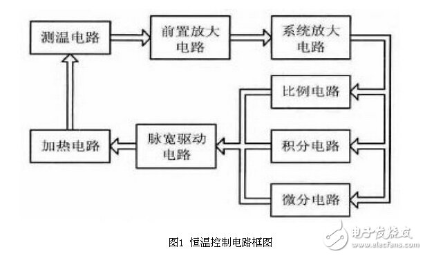
The circuit block diagram is shown in Figure 1. The temperature measurement circuit converts the current core temperature value into a voltage value. This value is a weak signal value and must be amplified to a suitable voltage output value by a high signal-to-noise ratio preamplifier circuit. The system is amplified, and then sent to the PID link for control output. The control output generates a width-adjustable pulse signal to drive the heating circuit to heat the sensor core. The greater the temperature difference between the current temperature of the sensor and the set temperature, the larger the error voltage signal. The longer the pulse width is turned on, the longer the heating power is, and vice versa, thus achieving constant temperature control.
2.1 Temperature and heating power
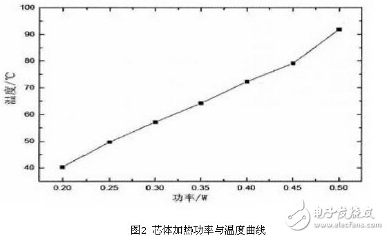
The sensor core temperature is related to the positive thermal energy loaded on the core and the negative thermal energy. If the temperature of the sensor core is maintained above the ambient temperature, the positive thermal energy loaded by the sensor core is derived from electrical energy. It is known from Joule's law that if the heating current on the given resistance R is I and the heating time is T, then I2 * R* T The electrical energy is converted into thermal energy; and the negative thermal energy loaded by the sensor core can be the thermal convection generated by the temperature difference between the sensor core and the surrounding environment and the thermal energy transfer caused by the heat conduction. The effect of this positive thermal energy and negative thermal energy on the temperature is reflected by the heating power and cooling power of the sensor core, which together determine the stable temperature of the sensor core. Assume that the sensor core working environment temperature is 25 ° C, the sensor core gas concentration response temperature is 80 ° C, because the negative thermal energy of heat conduction and heat convection loss is a certain measurable value and remains constant, then the core of the point environment The temperature is only related to the heating power. As mentioned above, the core can maintain the set point temperature if the current is suitable for the core. If the ambient temperature fluctuates up and down, the heating and cooling power of the core changes with temperature, so that the core continues to maintain the set point temperature. Only need to adjust the current on the core. In the environment of 25 °C, the relationship between the measured heating power and the core temperature is shown in Fig. 2. When the heating power is 0.45W, the core can work stably at the set temperature of 80 °C.
2.2 Temperature measurement
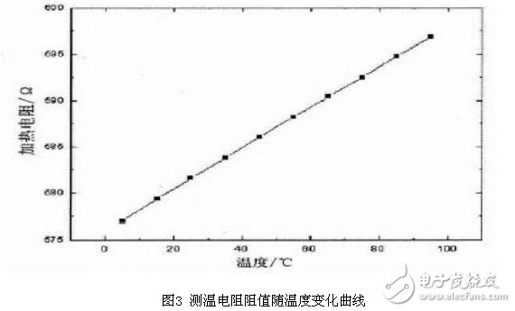
In order to more accurately measure the temperature of the sensitive core temperature field, a temperature measuring resistor and a heating resistor are integrated on the hydrogen sensitive core. The temperature resistance, heating resistor and hydrogen sense layout design are optimally coupled by temperature field simulation. Therefore, the temperature measuring resistor can truly reflect the current operating temperature of the hydrogen sensitive resistor. The temperature measuring resistor material is made of high-purity platinum resistance coating. The temperature characteristics of the measured temperature measuring resistor are shown in Figure 3. It can be seen from the figure that the temperature measuring resistor has a good temperature linear relationship. The temperature coefficient of the temperature measuring resistor is prepared by a thin film deposition process, and the temperature coefficient is not as large as the standard PT100, but does not affect the use.
The resistance is detected by the temperature measuring bridge, and the voltage signal reflecting the temperature is output. This signal is very weak in the control area. In order to improve the temperature measurement accuracy, a four-wire detection circuit is used to reduce the influence of the temperature of the platinum resistance lead and the platinum resistance current on the temperature measurement.
2.3 Temperature control loop
Usually the temperature system is a large inertia system with a large hysteresis, and often requires a differential link with advanced adjustment. The gas sensor core has a small volume. Whether it is heating or cooling, the core responds quickly to temperature. Proportional integral control can achieve good results.
2.3.1 Proportional link
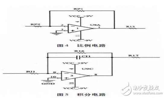
The proportional link has the ability to adjust quickly. The larger the proportional coefficient, the smaller the static difference is. The circuit is shown in Figure 4. The gain is -RP1 / RP2. When the test test scale factor is -4, the control effect is better.
2.3.2 Points Link
The integral link can eliminate the static error of the system. When the system has a steady-state error, the output of the integral link will continue to increase, so that the control effect is strengthened, thereby reducing the steady-state error. The smaller the integral coefficient, the more obvious the integral action and the higher the control precision. The integration circuit is shown in Figure 5. The gain is - 1 / RI1 * CI1 * S, where S is the pull operator. The adjusted time constant RI1CI1 is 4.7 s.
The PWM on/off control mode maximizes the use of heating power. At the instant of conduction, the heating voltage is completely applied to the heating resistor, and the current peak value is relatively large, so it is necessary to control the appropriate resistance of the heating resistor. In addition, the PWM control is completely turned on. Although it does not have a bad influence in this circuit application, in order to adjust the maximum heating power to achieve the maximum heating temperature, a Zener diode is used in the PID output to control the PID. The amplitude of the output voltage ensures that the PWM can output a dead band of a certain width.
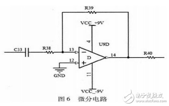
2.3.3 Differential circuit
The differential environment has a large response output to the rapidly changing input, which can improve the ability of the temperature control system to respond quickly to environmental temperature fluctuations. The differential link has the function of advanced adjustment. The specific circuit is shown in Figure 6.
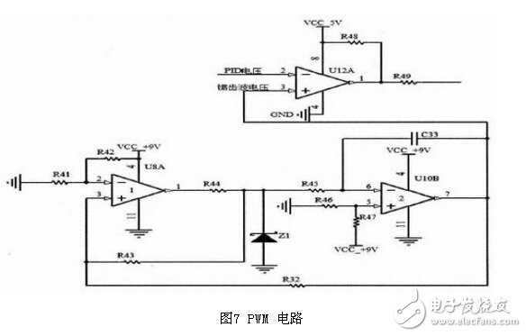
2.3.4 PWM generation circuit
The PWM circuit is built by simple discrete devices. The specific circuit is shown in Figure 7. It mainly consists of a comparator that generates a threshold-threshold waveform, and then generates a standard sawtooth wave through the charging and discharging of the integrating circuit. The sawtooth wave is compared with the output voltage of the PID link to generate a pulse. A waveform whose width is adjusted with temperature error, which is output to the driving heating circuit.
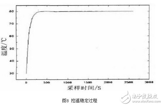
3 Experimental results
The prototype was subjected to a short-term test of stable dynamic processes and a long-term test of stable points. The short-time test prototype temperature curve is shown in Figure 8. It can be seen that the time when the prototype reaches 90% of the temperature set point is very short, about 120s, and the overall temperature control accuracy is within 0.15 °C. When the ambient temperature fluctuates, the temperature control point will follow the disturbance and will quickly return to the set temperature value, and the dynamic response is very fast.
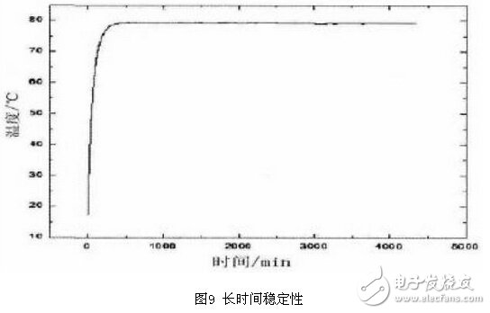
The long-term monitoring curve of the temperature control effect of the prototype is shown in Figure 9. From the figure, the overall temperature control accuracy is more obvious within 0.15 °C, indicating that the temperature control point of the prototype circuit does not drift with time, nor does it change slowly with the environment. Fluctuation drift.
4 Conclusion
PID pulse width temperature control circuit, using fewer components, simple adjustment, control accuracy can reach ± ​​0.15 ° C, fully meet the needs of gas sensor applications. It is especially suitable for aerospace products in terms of feasibility, reliability and safety, and can be applied in gas sensors.
Tinned Copper Clad Aluminum TCCA
Copper Clad Aluminum Tinned Wire,Tinned Copper Clad Aluminum Audio Cable,Tinned Copper Clad Aluminum Alloy Wire ,Copper Clad Aluminum Tin Plating
changzhou yuzisenhan electronic co.,ltd , https://www.yzshelectronics.com