With the increasing popularity of automotive radar, the overcrowded radio frequency spectrum in the urban environment will become a battlefield for spectrum competition. Radars will face combined attacks with unintentional or intentional interference, and designers must implement anti-jamming techniques as they would in combat.
Automotive radars are usually subject to denial or deceptive interference. Denial jamming blinds the victim vehicle's radar. This technique will reduce the signal-to-noise ratio, resulting in a decrease in the probability of target detection. On the other hand, deceptive interference will make the victim's radar "believe" that there is a false target. The victim vehicle's radar loses the ability to track real targets, so the behavior of the victim vehicle is seriously affected.

These interferences may originate from the mutual interference between car radars, or the use of cheap hardware to simply direct strong continuous wave (CW) signals to the victim vehicle radars and deliberate attacks.
Although the current interference avoidance technology may be sufficient to deal with today's situation, with the proliferation of radar sensors, cars will need to use flexible types of mitigation technology, or such technology in combination with interference avoidance methods. Flexible techniques include time-frequency domain signal processing or complex radar waveforms.
Radar waveform
The radar waveform is one of the key system parameters for judging the performance of the sensor in the presence of interference. Today's automotive radars in the 77 GHz frequency band mainly use FMCW-type waveforms. In FMCW radar, the CW signal linearly sweeps or chirps on the frequency of the radio frequency band. Figure 1 shows an example of an FMCW chirp sequence (CS) waveform.
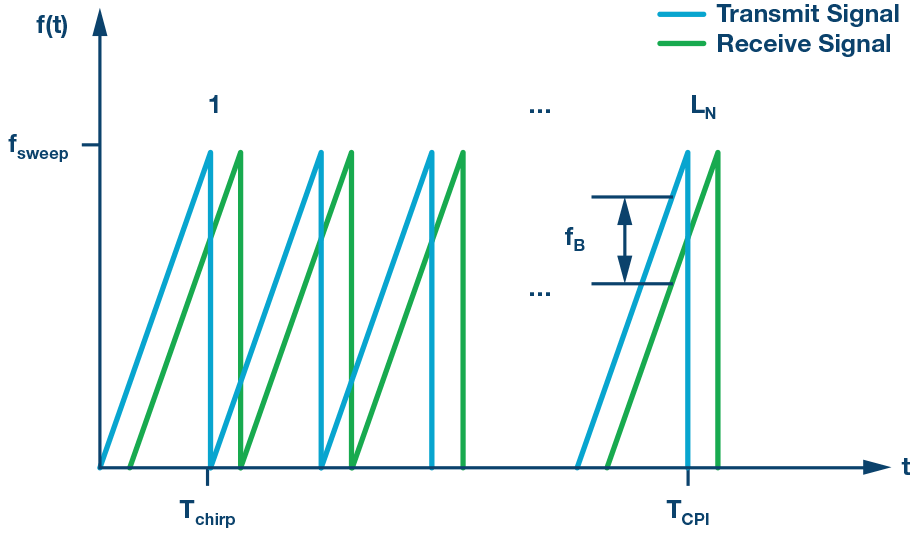
Figure 1. FMCW CS example
The frequency difference (fb, beat frequency) of the echo signal is proportional to the distance R to the target, which can be determined by the following relationship:

The impact of interference
In a dense radio frequency environment, interference occurs when the FMCW radar sensor is operating in the same part of the frequency band. A typical example of oncoming car interference is shown in Figure 2.
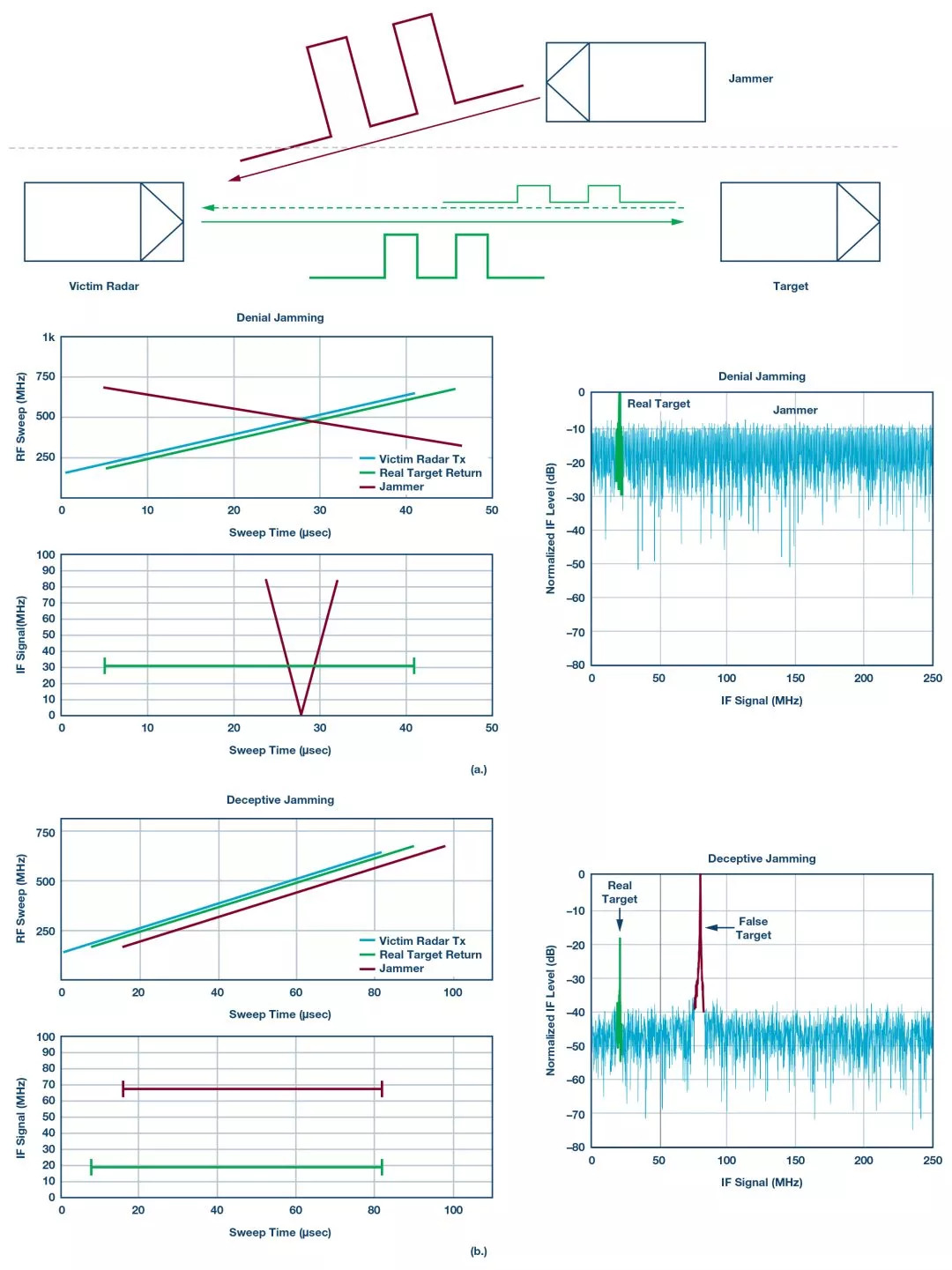
Figure 2. Example: a) FMCW rejection interference; b) FMCW deceptive interference
Rejection interference
Any FMCW-type strong jamming signal falling into the receiver bandwidth will increase the noise floor of the victim radar. Such rejection interference may cause small targets (ie, small radar cross section (RCS)) to disappear due to poor SNR.
Refusal interference can also be done deliberately, simply by shooting a strong CW signal to the FMCW radar of the victim vehicle. The impact on the victim radar is similar to the FMCW interference situation (see Figure 4).
Deceptive interference
If the jamming signal scan is synchronized but delayed along with the victim radar, then its effect will be to produce deceptive false targets at a fixed distance. This technique is very common in electronic warfare jammers. A similar type of oncoming car radar will become an unintentional jammer. However, the probability of time alignment between the victim radar and the jamming radar will be very small. A jammer delay offset that is less than the maximum range delay of the victim radar may look like a real target. For example, the maximum distance of 200 m requires the scan alignment error to be less than 1.3 μs. However, by installing complex electronic warfare-like equipment on an oncoming car platform, such deceptive attacks can be deliberately carried out.
More generally, deceptive jamming is based on the retransmission of the victim radar signal, but its delay and frequency are systematically changed. This can be incoherent (the jammer in this case is called a transponder) or coherent (the jammer in this case is called a repeater). The repeater receives, changes and retransmits one or more jamming signals, while the transponder transmits a predetermined signal when the jammer detects the target victim radar signal.
Complex attacks based on repeaters usually require digital radio frequency memory (DRFM). DRFM can perform coordinated range delay and Doppler gate drag attacks. Therefore, it will maintain the false target range and Doppler characteristics to deceive the victim radar.
Interference mitigation technology
Basic method: avoid
Basic radar interference mitigation techniques mainly rely on methods of avoiding interference. The goal is to reduce the possibility of space, time and frequency overlap, for example:
Space: The use of narrow electronic scanning beams can reduce the risk of interference. The typical field of view of the long-range car cruise control (ACC) radar is ±8°. Nevertheless, strong interfering signals can still cause effective interference through antenna side lobes.
Time: randomly generate FMCW chirp slope parameters to avoid periodic interference.
Spectrum: Randomly generate FMCW chirp start and stop frequencies to reduce the probability of overlap and interference.
The basic method of randomization will avoid accidental synchronization with other radars, but may not be so useful in dense RF environments. More and more radar sensors require more complex and flexible technology to mitigate interference.
Strategic approach: detect and fix
Another way to avoid interference is to use signal processing algorithms to repair the received waveform. Time-frequency domain technology can effectively deal with denial of interference attacks. In the case of oncoming car FMCW interference, the time for the jammer to scan all frequency slots is very short. This fast time-varying signal appears as a raised noise floor in the conventional FFT domain. The time-frequency domain signal processing technology transfers the signal to another domain, where it is easier to filter out interference than the FFT domain (see Figure 3).
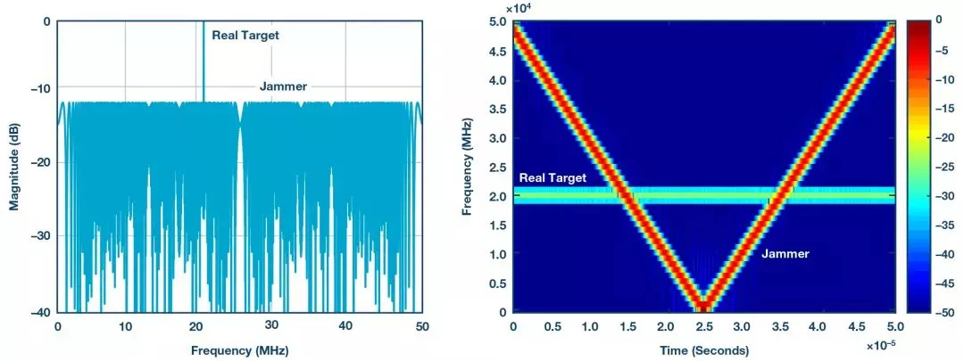
Figure 3. FFT and STFT domain representation of the radar echo IF waveform
For time-varying signals, short-time Fourier transform (STFT) can provide more information than regular FFT. STFT-based technology can be used to eliminate narrowband interference. STFT basically moves a window through the signal and obtains the FFT of the window interval. The signal is filtered in the frequency domain to remove interference components, and then converted back to the time domain.
Figure 4 shows a typical FMCW interference situation with overlapping radio frequency chirp sequences, and the resulting IF beat signal in the STFT domain.
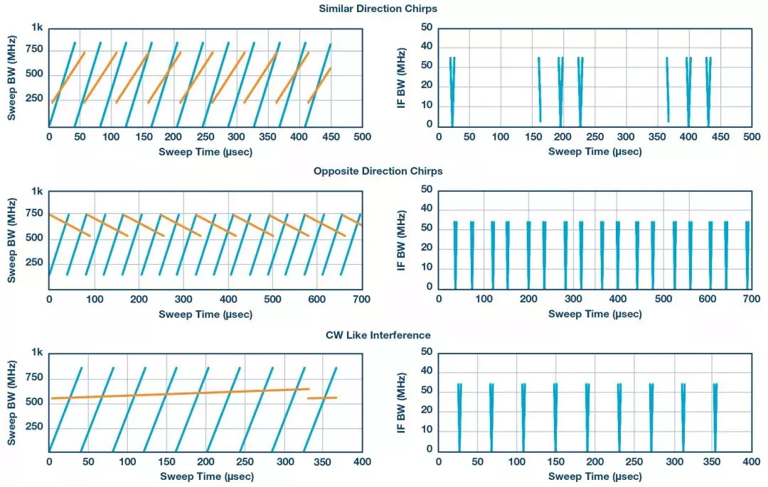
Figure 4. STFT domain, left: FMCW radar and jammer, right: IF domain
The right side of Figure 4 shows the IF domain, which is the final result of mixing the radar (blue) and interference (orange) signals. The horizontal line indicates the target, and the V-shaped vertical line indicates the presence of interference signals.
Interference FMCW in similar or opposite directions, or even slow chirp similar to CW, has similar effects on IF signals. In all these interference situations, the fast-moving V-shaped IF signal will increase the noise floor in the conventional FFT domain, as shown in Figure 3.
Amplitude-based masking can be used to filter out interfering signals in the STFT domain. Of course, the premise is that the front end and quantization part of the victim radar have sufficient dynamic range to simultaneously linearly process the stronger interference signal and the smaller expected target signal. See Figure 5.
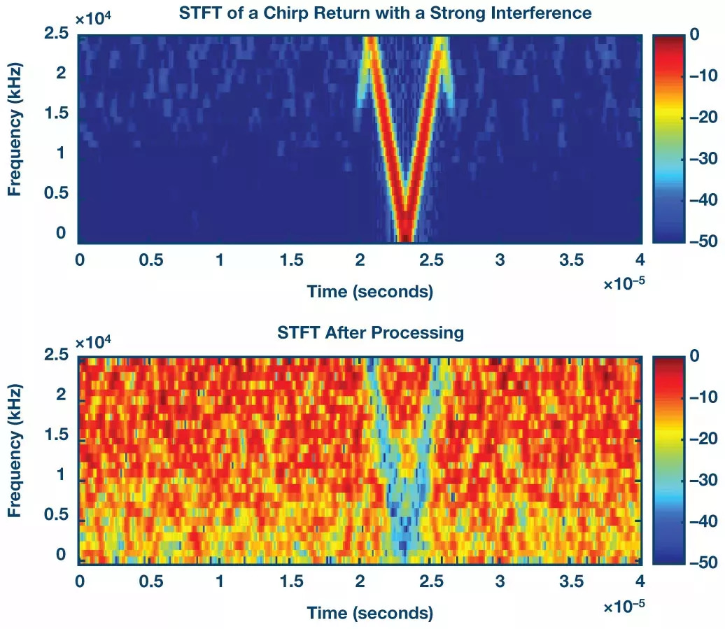
Figure 5. Amplitude-based masking in the STFT domain
The upper image of Figure 5 shows a strong interference signal, while the lower image shows the processed STFT. In the presence of strong interference, as shown in the image above, multiple real targets are not visible. In the image below, the V-shaped interference signal is eliminated; when transferred back to the time domain, the low SNR target is now recognizable.
In the rejection-type interference situation, STFT-based interference mitigation technology can be used to deal with strong interference. For deceptive jamming attacks, STFT alone cannot verify whether the return signal is true or false.
Encrypted radio frequency
The basic countermeasure to reduce the impact of repeater deceptive jamming attacks is to use low probability intercept (LPI) radar waveforms. The purpose of LPI radar is to spread the radiated energy over a wide frequency spectrum to avoid detection, usually using quasi-random scanning, modulation or frequency hopping sequence. FMCW is an LPI waveform. If phase encoding or encryption is introduced into frequency chirp, it can further reduce the probability of DRFM intercepting automotive radar signals.
The unique encrypted radio frequency characteristics of each radar sensor can verify the authenticity of the returned signal. Figure 6 shows a use case where there is a frequency offset and delay between two identical radars (installed on different cars), creating a false target in the victim radar. The jamming radar and the victim radar are aligned in time (same chirp slope and shorter offset).

Figure 6. Interference caused by the same radar with frequency offset and delay
In this case, the phase-coded FMCW radar can provide high anti-jamming robustness. The use of orthogonal codes also makes MIMO radar operations feasible, thereby supporting simultaneous transmission of multiple waveforms.
Coding requirements:
Code length: The goal is to use a short sequence to achieve the minimum distance sidelobe level. A PRN sequence length of 1024 results in a peak side lobe level (PSLL) of approximately 30 dB (10log1024). The transmit code and receive filter weights can be optimized to improve PSLL at the expense of SNR.
Good cross-correlation characteristics: In order to achieve good isolation between sensors, the cross-correlation coefficient of members of a set should be zero.
Anti-Doppler effect capability: The performance of phase-coded radar may be affected by Doppler frequency shift. The binary code has poor tolerance to the Doppler effect. The performance degradation rate of polyphase codes is slower than that of binary codes.
The number of different codes available: the larger scale is better, and each radar sensor can be assigned a unique code.
Figure 7 shows the radar echo without phase encoding. The interference signal is shown as a false target. When the PRN sequence is used to phase-encode the transmitter FMCW waveform, the interference signal can be suppressed, as shown in Figure 8.
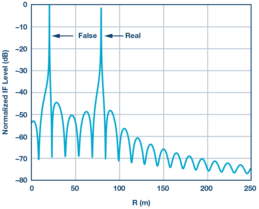
Figure 7. Radar echo without phase encoding for authentic and false targets
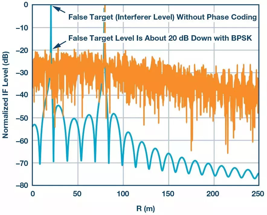
Figure 8. Radar echo with and without phase encoding
This method affects the dynamic range. However, the radar signal processor can use phase-encoded FMCW on several chirp signals to mark false targets and then switch back to normal operation.
Conclusion and future trends
The use of advanced signal processing algorithms and complex waveform generation technology can alleviate interference in crowded car radar sensor environments. STFT-based signal processing technology can be used to deal with denial-type attacks. With the help of processing gain and interception avoidance measures, phase-encoded FMCW provides an additional layer of defense against both incoherent and coherent spoofing attacks. Table 1 is a summary of mitigation techniques.

Table 1. FMCW-based automotive radar mitigation technology
The above-mentioned interference mitigation principles for automotive radars are also applicable to other radar sensor environments, such as robots, road toll collection, GPS, drone landing or collision avoidance systems.
Currently, automotive radar sensors operate in non-cooperative mode and do not communicate with each other. Although the cooperative mode of operation requires industry-wide coordination, arbitration between radar sensors can help solve interference problems.
The future radar concept including sensor cooperation will be the fusion of communication nodes and radar sensors. Future radars that use complex waveforms can also include information in the radar signal. The same hardware can be used for both radar and communications (RadCom).
RadCom: a single system where radar and communication functions are performed simultaneously
Multi-user capability, no interference
Use OFDM or similar communication codes to encode the radar signal, which provides the possibility to include information in the radar signal
The OFDM-based radar transmission signal allows the two to be carried out at the same time
ADI's 5G millimeter wave transceiver signal solution has a bandwidth exceeding GHz and beam steering capabilities, and may become a potential candidate for the RadCom system concept.
ADI is in a unique position to develop the most advanced radar sensors and 5G millimeter wave solutions, paving the way for future RadCom systems.
MW01 Smart Watch
Mw01 Smart Watch,Mw01 Smartwatch,Smart Watch Mw01,Smartwatch Mw01
everyone enjoys luck , https://www.eeluck.com