Because the hull is affected by the waves, random sway (rolling, pitching, and yaw) will cause the antenna to sway, which will easily cause the tracking performance of the narrow beam antenna to drop and even cause the target to be lost. In order to accurately track the target and reduce the disturbance caused by the carrier motion to the antenna tracking, it is necessary to establish a set of anti-disturbance stabilization system, so that the antenna output isolating the hull disturbance and stabilized in the inertial space coordinate system. Ensure system tracking and tracking performance requirements.
In order to effectively realize the anti-disturbance function, the traditional scheme needs to adopt multi-mode compensation at the same time, and use at least 6 rate gyros to detect the three-dimensional disturbance information of the hull and the active rotation information of the antenna, according to the three axes of the antenna (azimuth axis, pitch axis, cross-cut) The shaft) structure combines feedforward open loop compensation and feedback closed loop compensation to achieve isolation of disturbances. The design of the scheme is complicated, the gyro is used in a large amount and the redundancy is insufficient.
1 Influence of hull three-dimensional disturbance on the visual axis of three-axis antennaThe triaxial antenna system (transverse axis C, azimuth axis A, pitch axis E) is based on a conventional AE type frame, superimposed perpendicular to the pitch axis on the pitch axis, and the transverse axis is perpendicular to the axis . When the pitch angle E=0°, the transverse axis coincides with the azimuth axis; when the elevation angle E=90°, the transverse axis is perpendicular to the azimuth axis.

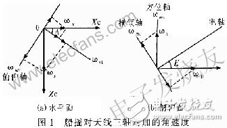
When the hull expresses the disturbance with an angular velocity vector ωz = (ωpωyωh). Among them: ωy is the ship's roll speed, ωp is the ship's pitch speed, and ωh is the ship's heading speed. The change in the ship's rocking parameters is converted to the velocity components of the heel, azimuth, and pitch axes, as shown in Figure 1. Let ωRE be the azimuth speed attached to the ship's rocker, ωRC be the additional heeling speed of the ship's rocker, and ωRE be the pitching speed of the ship's rocking deck coordinate system: OXc is the bow line, è‰ is positive, OYc is the vertical deck plane, upward For the positive, OZc is determined by the right hand rule.
Available from Figure l(a):

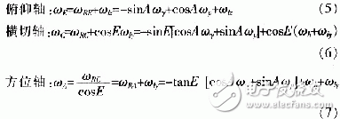
When A = 0°, the pitch speed is ωp=0, and only the roll amount ωy; when A=90°, the roll speed is ωy=0, and only the pitch amount ωp. Under the joint action of the antenna active drive and the carrier disturbance, the total rotational speed of each axis of the antenna is:

Equations (2) to (4) are the reflections of the hull three-dimensional disturbance on the three axes of the antenna. The servo control system can use open-loop compensation to eliminate its influence on the antenna tracking. Equations (5) to (7) are the total rotation information of the three axes of the antenna in the inertial space, and the servo control system can eliminate the influence on the antenna tracking by using a closed loop method. Therefore, trying to correctly measure this information and adopt appropriate control modes to suppress the disturbance to make the antenna fast and stable tracking target is the core of the anti-disturbance design of the servo system.
2 anti-disturbance designThe ship shake disturbance is introduced into the servo system as an interference signal. The principle of stable control is to detect such interference, and the closed loop or open loop method is adopted to reduce or eliminate the influence. The disturbance isolation methods mainly include: rate gyro feedforward compensation, rate gyro feedback control, and composite control. Since the gyro closed-loop control is essentially an error adjustment method. The gyro measures the integrated disturbance information and cannot distinguish between the disturbance information component and the follow-up information component. Therefore, while suppressing the disturbance information, the gyro loop also dynamically suppresses the active motion of the antenna, reduces the response speed of the system, and deteriorates the stability of the system. Relatively speaking, the feedforward compensation is an open loop adjustment method. The measured disturbance information is added to the input end of the speed loop, so that the antenna shaft rotates at a speed opposite to that of the ship to compensate. At the same time, since the structure and parameters of the tracking loop are not changed, the bandwidth of the system is not affected, and the stability of the loop is good.
2.1 Compensation principle
The feedforward compensation method is to rotate the antenna in the opposite direction to the disturbance to overcome the influence of the disturbance. According to the reflection of the above three-dimensional disturbance on the three axes of the antenna, the installation position of the gyro is reasonably designed to induce the movement speed of the antenna three axes relative to the inertial space caused by the ship shake, and the motion speed is used as the disturbance to the antenna, and the speed is added. The input end of the ring makes the rotation of the antenna shaft opposite to the direction of the ship and the same amount of speed, which acts as a restraining effect.
2.2 Control implementation
The three-axis stability control of the antenna tracking device uses a speedometer as the speed feedback, the encoder acts as a position feedback, and the ship shake disturbance is fed forward to the speed loop via the rate gyro detection. The working principle block diagram is shown in Figure 2.

In Figure 2, K1W1 is the position loop correction control transfer function; K2W2 is the speed loop closed-loop transfer function, F(S) is the compensation channel transfer function, and the system transfer function is:

It can be known from equation (8) that the loop following capability is
![]()
Decision, and ship shake disturbance elimination ability
![]()
Decide. It can be seen from the second term that the amount of motor drive angular velocity that eliminates ship shake disturbance is composed of two parts, one is the current angular velocity (target stationary) in which the visual axis is disturbed in the inertial space. The second is the motor drive angular velocity given by the speed loop by the current moment disturbance given by the compensation loop.
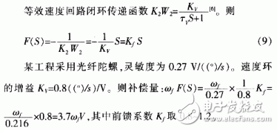
According to the principle of complete invariance, when (1+F(S)K2W2)ωf, that is, F(s)=-1/K2W2, complete isolation of the ship shake disturbance is achieved, that is, when the condition is satisfied, regardless of the disturbance amount ωf How big, no effect on the output. However, the speed loop K2W2 contains integral links, inertia links, and second-order links. If complete invariance is to be achieved, there must be many differential links in F(S), so that the output of F(S) will be full of noise. The system simply can't work. But achieving local invariance is possible. That is, low-order differential is used instead of high-order differential, and its coefficient satisfies certain conditions to meet the requirements of system accuracy.
In actual use, the feedforward compensation coefficient is reasonably selected to maximize the feedforward loop to eliminate the current disturbance. On the basis of this, combined with the loop following ability, the deviation of the visual axis is effectively eliminated, and high-precision tracking is realized. Therefore, the feedforward loop acts as a coarse adjustment, while the position tracking loop can be referred to as fine adjustment.
2.3 Engineering Applications
2.3.1 Installation and Measurement
The speeds added to the azimuth, heel, and pitch axes due to hull sway are measured using three rate gyros for open loop compensation.
The tilting gyro is mounted on the azimuth turret. The sensitive axis is parallel to the pitch axis of the antenna. The gyro moves with the azimuth axis. It is sensitive to the rotation of the azimuth axis, the rotation of the pitch axis, the heading speed of the hull, etc. It is sensitive to the hull roll. The pitch rate, as shown in equation (2), can directly perform open-loop feedforward compensation on the pitch axis.

Analysis of the perturbation of the heel axis (formula (3)) and the perturbation of the azimuth axis (formula (4)) cannot be directly measured with a gyroscope and can be obtained by an indirect method. CosAωy+s-inAωp and ωh are respectively measured by two gyros, and equations (3) and (4) are obtained mathematically according to the pitch angle E. Thus, the rate gyro measuring the ωh component is mounted on the azimuth base (not rotating with the azimuth axis), the sensitive axis is parallel to the azimuth axis, and the output is mainly the heading rate information of the hull. The rate gyro measuring the cosAωy+sinAωp component is mounted on the azimuth turntable (rotating with the azimuth axis), and its sensitive axis is parallel to the roll axis.
2.3.2 Testing and analysis
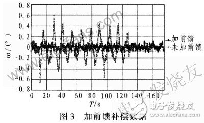
A shipboard three-axis antenna control system uses an anti-disturbance design. Swing experiments were carried out at sea, under typical sea state parameters (swing amplitude ± 6 °, rocking period 12 s). The antenna points to the satellite self-tracking, rotating the ship's heading, and measuring the ship's rock isolation when the ship is shaken. At this time, the antenna azimuth is turned to 90° or 270°; the ship shake isolation of the heel axis is measured to make the antenna azimuth turn to 0° or 180°. The isolation test results are shown in Figure 3. In the figure, curve series 1 indicates that feedforward tracking data is added; curve series 2 indicates no feedforward tracking data. The test results are: ship shake isolation of 46.4 dB; tracking accuracy of 0.031 °. From the above data analysis, it can be concluded that the open-loop compensation scheme fully meets the performance requirements of the system design.

Feedforward compensation does not change the pole and closed loop zero of the original closed loop system. Therefore, it does not affect the servo bandwidth and stability of the system. When the project is used, the application of feedforward compensation and feedback control is combined to simplify the system and improve the reliability and service life of the device while ensuring the function and performance. The actual use effect is remarkable.
About this item
1.Axial-tech Fan Design has been enhanced with more fan blades and a new rotation scheme
2.2.9-slot design expands cooling surface area compared to last gen for more thermal headroom than ever before
3.Super Alloy Power II includes premium alloy chokes, solid polymer capacitors, and an array of high-current power stages
4.MaxContact heat spreader allows 2X more contact with the GPU chip for improved thermal transfer
5.Reinforced frame prevents excessive torsion and lateral bending of the PCB
6.FanConnect II equips a hybrid-controlled fan header for optimal system cooling
7.Vented backplate prevents hot air from recirculating through the cooling array
The ROG STRIX Radeon RX 6700 XT merges an industry-leading cooling solution with high-end power performance and additional creature comforts.
A massive heatsink is cooled by Axial-tech fans that utilize a new rotation scheme.
And top-shelf capacitors, chokes, and MOSFETs effortlessly deliver hundreds of watts at a millisecond's notice.
rx6900xt,amd rx 6900xt,radeon rx 6900xt,amd radeon rx 6900xt,rx6900xt price
Easy Electronic Technology Co.,Ltd , https://www.yxpcelectronicgroups.com