0 Preface
The global climate warming crisis and energy shortage are further promoting the popularity of LED lighting. LED lighting has the characteristics of environmental protection, high luminous efficiency and long life, but LED lighting still exists in the complete replacement of incandescent lamps with wall dimmers. Poor compatibility is inherently inadequate. The main reasons are: 1) the existing dimmers are designed for incandescent lamps, while the incandescent lamps are purely resistive; LEDs as solid-state semiconductor lighting devices require constant DC current driving, so LED lighting is generally The driver needs to convert from AC 110V/220V to the required DC current; 2) There are many types of dimmers, and the working principle is different, including front cutting type, rear cutting type and intelligent type; 3) Types of LED illuminators There are also many. In this way, different types of dimmers are matched for different LED illumination; LED drivers face enormous challenges; among them, reliability and safety are particularly important. Lighting is a consumer electronics product that directly contacts thousands of households. Not only should the price be appropriate, but more importantly, it must be safe and reliable. Even if any component fails or the dimmer does not match the LED, it will not cause leakage or overheating. Any safety failure such as overcurrent.
In response to the development of the LED lighting market, a number of IC manufacturers have introduced driving solutions for dimming LED lamps. The iW3610 described in this article is a digital controller compatible with traditional front and rear phase-cut dimmers. It automatically recognizes the phase-cut dimmers and works with different modes to keep the entire system in an optimized state.
1 LED lighting driver design points
LED is a unidirectional current type solid-state semiconductor light-emitting device, which is a branch of a conventional diode; therefore, the LED also has the characteristics of a diode: 1) the operating junction temperature must be within a prescribed range to ensure its normal working life; 2) Only when the voltage it is subjected to exceeds the forward voltage, the LED begins to pass current and emits light; as a light-emitting device, LED illumination has other characteristics:
1.1 Lighting requirements:
a. The current adjustment accuracy is high; b. There is no flicker and glare; C. The current ripple is stable.
1.2 Thermal design points:
a. Non-isolated driver for heat sink design and cost control; b. High efficiency driver to reduce power dissipation; c. Overheat regulation to regulate output flux when temperature exceeds safe junction temperature.
1.3 Safety and reliability points:
a. Failure of any device (short circuit, open circuit, floating) should result in shutdown protection of LED lighting; b. reliable overheat and overcurrent protection; c. LED open and short circuit protection.
Of course, to popularize LED lighting to thousands of households, cost is the most important consideration. LED products are both reliable and compact, and efficient and low-cost.
2 Difficulties in LED dimming lighting applications
Compared with traditional incandescent lamps, LED lighting has the advantages of environmental protection, high luminous efficiency and long life. However, LED lighting still has the disadvantage of poor compatibility in completely replacing incandescent lamps with in-wall dimmers. Traditional dimmers are used to drive purely resistive loads. There are many types of dimmers, including leading edge phase-cut dimmers, trailing edge phase-cut dimmers, smart dimming, etc., and the power is relatively large (200W~600W). A resistive or resistive load is required to stabilize the dimmer; when connected to a capacitive load, the dimmer may not function properly.
For thyristor phase-cut dimmers, it is difficult to satisfy the task of using a simple bleeder circuit (BLEEDER) to match different thyristor dimmers. Traditional dimmers have relatively large power (200W~600W). SCRs need a certain holding current to maintain their conduction. In low-power LED driving applications, there is generally no guarantee that there is enough input current to maintain controllability. Silicon works stably. In this way, it is possible to have multiple conductions, and thus the voltage and phase-cut signal for supplying the LED drive are unstable, and if the dimming signal is not handled well, the LED will blink.
In addition, in the European and American markets, the trailing edge phase-cut dimmers and halogen lamps are also widely used. Halogen lamps require electronic transformers for constant voltage control and soft-start to improve reliability, but halogen lamps are far less efficient than LED lamps, so many users also want to use dimmable LEDs to replace halogen lamps and electronic transformers.
Since the trailing edge phase-cut dimmer needs to be matched with a capacitive electronic transformer, its design and process are more complicated than ordinary thyristor dimmers. There is a precise time constant circuit inside to control the FET. Breaking to achieve the effect of the trailing edge phase cut, a stable voltage is required for these circuits to work; because the switching device used in this dimmer is a field effect transistor, a larger value of X capacitor is generally connected in parallel to protect the field effect. Tube, this increases the difficulty of detecting the phase cut at the falling edge of the sine wave. Therefore, the LED driver designed for the trailing edge phase-cut dimmer must be able to ensure the internal circuit operation of the dimmer at any phase-cut position, and provide a low impedance to accurately detect the phase-cut position, and can not affect the LED. Drive conversion efficiency.
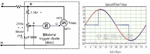
Figure 1 Internal circuit and phase-cut waveform of thyristor dimmer
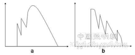
Figure 2. Multiple turns on the thyristor holding current in a simple Bleeder circuit.
4 intelligent digital dimming controller iW3610
iWatt's digital dimming control chip uses high-precision primary constant current control, eliminating the need for optical couplers and a wide range of secondary feedback control components; power conversion operating frequency up to 200kHz, which facilitates small-volume, high-power density design; The detection technology of the chopper dimmer also improves the power factor and harmonic current; the output ripple current is small, optimizing the luminous efficiency of the LED; the built-in multiple protection, the programmed over-temperature protection of the external NTC.
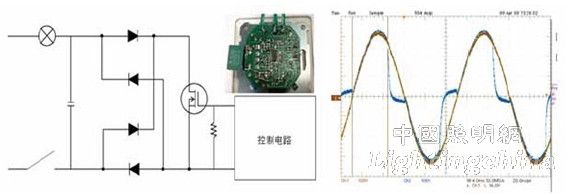
image 3
The iW3610's chopper circuit is designed for the characteristics of thyristors and FET dimmers. As shown in Fig. 4, the circuit composed of RcLcQcD1D2 can not only stabilize the dimmer, but also improve the power factor through the Boost circuit. The digital circuit inside the IC judges the type of the phase-cut signal by detecting the rate of change of the voltage, thereby intelligently judging The dimmer that it is equipped with.
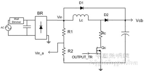
Figure 4
When the iW3610 detects the dimming signal of the thyristor phase, it will work in the leading edge phase-cut mode. As shown in Figure 5, when the TRIAC is turned off, the IC's Output_TR is high, turning the MOSFET on, which is equivalent to connecting the BLEEDER resistor to the output of the dimmer, because the impedance of the BLEEDER is different from the conventional tungsten wire. The lamp is equivalent; when the thyristor is turned on, the Ouput_TR will output a set of high frequency control signals, the chopper circuit operates in the high frequency switching state, and the chopper circuit draws more current from the input terminal to maintain the thyristor operation. Most of the absorbed energy is transferred to the primary capacitor through the Boost circuit. The IC adjusts the working time of the chopper circuit for different input phase-cut signals, avoiding multiple conduction of the thyristor.
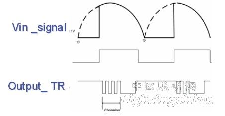
Figure 5