S7-200 has two PTO/PWM generators to create high-speed pulse train (PTO) or pulse width adjustment (PWM) signal waveforms.
When configuring an output for PTO operation, a 50% duty cycle pulse train is generated for stepping motor or servo motor
In order to simplify the use of position control functions in user applications, the position control wizard provided by STEP7--Micro/WIN can help you complete the configuration of PWM, PTO or position control modules in a few minutes. The wizard can generate position instructions, which users can use to provide dynamic control of speed and position in their applications.
2. Open loop position control is used for basic information of stepper motor or servo motor
When configuring PTO output with the help of the position control wizard, the user needs to provide some basic information, which are introduced one by one as follows:
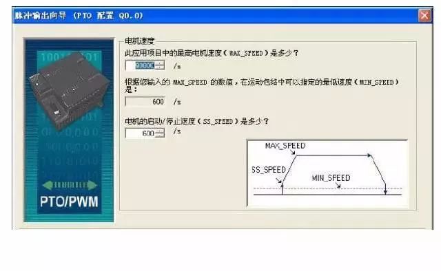
â‘´ Maximum speed (MAX_SPEED) and start/stop speed (SS_SPEED)
Figure 1 is a schematic diagram of these two concepts.
MAX_SPEED is the maximum allowable operating speed, which should be within the range of motor torque capacity. The torque required to drive the load is determined by friction, inertia, and acceleration/deceleration time.
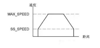
Figure 1 Maximum speed and start/stop speed
SS_SPEED: This value should meet the ability of the motor to drive the load at low speed. If the value of SS_SPEED is too low, the motor and load may sway or tremble at the beginning and end of the movement. If the value of SS_SPEED is too high, the motor will lose pulses when starting, and the load will overspeed the motor when it tries to stop. Generally, the SS_SPEED value is 5% to 15% of the MAX_SPEED value.
⑵Acceleration and deceleration time
Acceleration time ACCEL_TIME: the time required for the motor to accelerate from SS_SPEED speed to MAX_SPEED speed. Deceleration time DECEL_TIME: The time required for the motor to decelerate from the MAX_SPEED speed to the SS_SPEED speed.

Figure 2 Acceleration and deceleration time
The default setting of acceleration time and deceleration time is 1000 milliseconds. Generally, the motor can work in less than 1000 milliseconds. See Figure 2. These two values ​​should be set in milliseconds.
Note: The acceleration and stall time of the motor should be determined by testing. At the beginning, you should enter a larger value. Decrease this time value gradually until the motor starts to stall to optimize these settings in your application.
⑶ mobile envelope
An envelope is a pre-defined movement description, which includes one or more speeds that affect the movement from the start point to the end point. An envelope is composed of multiple segments, and each segment includes an acceleration/deceleration process to reach the target speed and a series of fixed number of pulses running at a constant speed at the target speed. The Position Control Wizard provides a mobile envelope definition interface, where you can define every mobile envelope for your application. PTO supports a maximum of 100 envelopes.
Defining an envelope includes the following points: â‘ Select the operation mode; â‘¡Define indicators for each step of the envelope. â‘¢ Define a symbolic name for the envelope.
â‘´Choose the envelope operation mode: PTO supports relative position and continuous rotation at a single speed. As shown in Figure 3, the relative position mode means that the end position of the movement is the number of pulses calculated from the starting point. Single-speed continuous rotation does not need to provide the end position. PTO will continue to output pulses until other commands are sent, such as reaching the origin and requesting stop pulses.
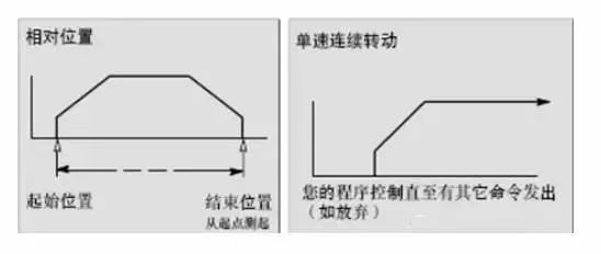
Figure 3 Operation mode of an envelope
⑵ Steps in the envelope
A step is a fixed distance of the workpiece movement, including the distance of acceleration and deceleration time. Each envelope of PTO allows up to 29 steps.
Each step includes several indicators such as target speed and end position or number of pulses. Figure 4 shows one-step, two-step, three-step, and four-step envelopes. Note that the one-step envelope has only one constant speed section, the two-step envelope has two constant speed sections, and so on. The number of steps is consistent with the number of constant speed sections in the envelope.
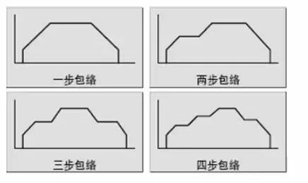
Figure 4 Schematic diagram of the number of steps of the envelope
7.2.5 Programming with Position Control Wizard
The position control wizard of STEP7 V4.0 software can automatically process single-segment pipeline and multi-segment pipeline of PTO pulse, pulse width adjustment
Control, SM position configuration and create envelope table.
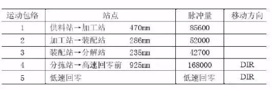
This section will give an example of a simple task implemented on YL-335A, explaining the method and steps of programming using the position control wizard. Table 1 is the motion envelope needed to realize the operation of stepper motor on YL-335A.
Table 1 Motion envelope of stepper motor operation
1. The steps for programming using the position control wizard are as follows:
1) Select option configuration for S7-200 PLC to set PTO/PWM operation.
In the STEP7 V4.0 software command menu, select Tools→Position Control Wizard and select Configure S7-200 PLC
Set PTO/PWM operation, as shown in Figure 5.
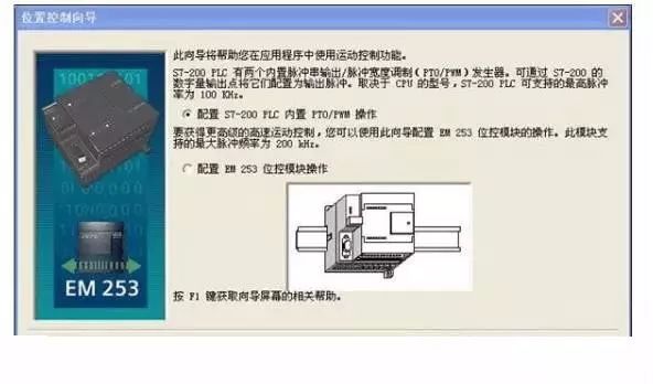
Figure 5 Position control wizard start interface
2) Click "Next" to select "QO.0", and then click "Next" to select "Linear pulse output PTO)".
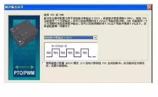
Figure 5 Select PTO or PWM interface
3) After clicking "Next", enter the MAX_SPEED and SS_SPEED speed values ​​in the corresponding edit boxes. Enter the maximum motor speed "90000" and set the motor start/stop speed to "600". At this time, if you click the gray box corresponding to the MIN_SPEED value, you can find that the MIN_SPEED value is changed to 600. Note: The MIN_SPEED value is calculated. The user cannot enter other values ​​in this field.
Lcd Tonch Screen For Iphone 8,Lcd Touch Screen For Iphone 8P,Lcd Display For Iphone 8P,Mobile Lcd For Iphone 8P
Shenzhen Xiangying touch photoelectric co., ltd. , https://www.starstp.com