Electromagnetic environment testing is a basic work of electromagnetic spectrum management. It is widely used in all aspects of electromagnetic spectrum management such as radio station location selection, frequency assignment, radio control and electromagnetic environment estimation. Mastering scientific test methods and accumulating practical experience is critical to microwave electromagnetic environment testing. This article combines the specific work practice, taking "HP8593 monitoring direction finding system" as an example (other systems can refer to carry out) to introduce the basic method of microwave electromagnetic environment testing.
1 Standards for testingThe standards for microwave electromagnetic environment testing are mainly GB 13616-92 "Electromagnetic Environmental Protection Requirements for Microwave Relay Stations" and GB 13619-92 "Interference Calculation Methods for Microwave Relay Communication Systems".
2 test system componentsSetting up the corresponding test system according to different test tasks is the first step to successfully complete the electromagnetic environment test task.
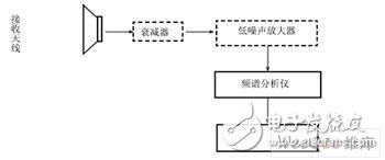
The HP8593 microwave electromagnetic environment test system (shown in Figure 1) with HP8593 spectrum analyzer is composed of wideband standard horn antenna, high frequency attenuator, microwave low noise amplifier, microwave low loss cable, HP8593E spectrum analyzer and portable It is composed of computers and other equipment, and can complete the electromagnetic environment monitoring in the frequency band of 1 GHz to 18 GHz.
It is worth noting that the test instrument such as spectrum analyzer should meet the requirements of GB6113 and be verified by the metrology department to ensure the accuracy of the test data.

Figure 1 HP8593 microwave test system
3 test system feasibility demonstrationAccording to the sensitivity of the receiving device in the tested microwave frequency band, the feasibility test of the built test system is carried out to confirm whether the system meets the test requirements that “the sensitivity of the test system must be higher than the sensitivity of the microwave receiving deviceâ€. Feasibility argumentation is a prerequisite for ensuring that the electromagnetic environment monitoring work is scientific, authentic and effective.
(1) Test system performance demonstration
The performance of the electromagnetic environment test system is mainly reflected in the receiving sensitivity, that is, the ability to receive weak signals. Receiver noise figure and sensitivity are two important parameters to measure the receiver's ability to receive weak signals, and can be converted to each other.
Receiver sensitivity is the receiver's ability to monitor weak signals at a specified bandwidth, in μV or dBμV; and noise figure is the additional noise generated inside the receiver (or spectrum analyzer) that is proportional to the theoretical heat of the input and the input itself. The ratio of noise is a dimensionless parameter, generally in dB. which is:
FN=NO/GNI 1
Where: FN is the noise figure;
NI is the input theoretical thermal noise power, NI=kT0B, k is the Boltzmann constant, T0 is the absolute temperature of the room temperature, and B is the effective noise bandwidth of the receiver (or the resolution bandwidth of the spectrum analyzer);
NO is the output noise power;
G is the circuit system gain.
The output noise of the circuit divided by the gain is the equivalent noise input of the circuit, so NI FN is the input noise power of the equivalent circuit. which is:
NI FN =kT0B FN
In receiver applications, kT0B FN represents the noise power at the input of the receiver, and the signal level must exceed this noise power. If S/N=1, the input signal power is equal to kT0B FN, as expressed in logarithm form:
10lgNI=10lgkT0B=-174+10lgB(dBm) 2
If B=1Hz, then: 10lgNI=-174+10lgB=-174(dBm/Hz);
If B = 1 kHz, then: 10 lgNI = -174 + 10 lgB = -144 (dBm / kHz).
If S/N=1 and the receiver noise figure is NF=10lgFN, the sensitivity of the receiver (or spectrum analyzer) is:
SN=10lgkT0BFN=-174+10lgBFN(dBm/Hz) 3
If B=1Hz, then: SN=-174+NF(dBm/Hz);
If B = 1 kHz, then: SN = -144 + NF (dBm / kHz).
The typical value of the noise figure of the HP8593E spectrum analyzer is 32dB, that is, NF=10lgFN=32. Then, under the condition that the front end of the spectrum analyzer is not attenuated, the receiving sensitivity is (if the front end attenuation is set to 10 dB, the sensitivity of the spectrum analyzer is reduced by 10 dB):
S=10lgkT0BFN=-174+10lgBFN = -174+32+10lgB.
If B = 1 Hz, then: S = -142 (dBm / Hz);
If B = 1 kHz, then: S = -112 (dBm / kHz).
For weaker signals, adding a low noise amplifier to the front of the spectrum analyzer will significantly increase the sensitivity of the receiving system.
(2) Test system sensitivity argument
In this test system, the spectrum analyzer receiving sensitivity is: S=-142 (dBm/Hz), which meets the requirements of GB13616-92 "Microwave Relay Station Electromagnetic Environmental Protection Requirements", DH Microwave Low Noise Amplifier Gain G is 30dB, Noise Coefficient Is 5. Then, the noise power at the output of the high-frequency low-noise amplifier (ie, the minimum signal level power) is given by Equation 3, which can be expressed as a logarithm:
SNo=10lgkT0BGFN
=-174+10lgBFN+G =-174+5+30+10lgB
If B=1Hz, then: SNo=-174+5+28=-141(dBm/Hz);
If B = 1000 Hz, then: SNo = -174 + 5 + 28 + 30 = -111 (dBm / kHz).
This value is higher than the receiver sensitivity of the analyzer, that is, the HP8593E spectrum analyzer can receive reliably for the air signal amplified by the low noise amplifier. The receiving sensitivity of the low noise amplifier is 169dBm. Considering the gain of the antenna, the ability of the test system to receive small signals, that is, the minimum signal level that can be received at the antenna interface can be expressed as:
Pr=low noise amplifier receiving sensitivity-antenna gain G2+ cable loss 1.5dB
which is:
*1300 MHz to 1800 MHz band:
Pr = -169-8.5+1.5=-176 (dBm/Hz);
*3700 MHz to 4200 MHz band:
Pr = -169-10.8 + 1.5 = -178.3 (dBm / Hz);
*4400 MHz to 5000 MHz band:
Pr=-169-11.1+1.5=-178.6(dBm/Hz);
*12.55 GHz to 12.85 GHz band:
Pr = -169-12.7 + 1.5 = -180.2 (dBm / Hz).
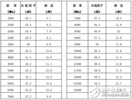
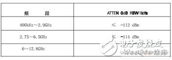
According to the "DH30010T2 Wideband Dual Ridge Horn Antenna Specifications" in Table 1, the Pr of other frequency bands can be calculated. Table 2 shows the average noise level of the HP8593E spectrum analyzer.
The above argument shows that the sensitivity of the test system is higher than the sensitivity of the receiving equipment such as radar and microwave working in the microwave frequency to be tested, and the relevant test requirements can be met.

Table 1 DH30010T2 broadband double ridge horn antenna technical indicators

Table 2 Average noise level of the HP8593E spectrum analyzer
4 Test methods and procedures(1) Selected test points
12V100Ah Lithium Ion Battery,Deep Cycle Solar Battery,2V 100Ah Lifepo4 Battery,12V 100Ah Lifepo4 Battery Pack
Jiangsu Zhitai New Energy Technology Co.,Ltd , https://www.jszhitaienergy.com