LPWAN, or LPN, is called the LowPower Wide Area Network or LowPower Network and refers to a wireless network. This wireless network emphasizes low power and long range and is typically used for battery-powered sensor node networking. Because of its low power consumption and low speed, this network is distinct from other wireless networks (such as WiFi, Bluetooth, etc.) for commercial and personal data sharing.
In applications, LPWAN can be built as a private network using a concentrator, or it can be connected to a public network using a gateway.
LPWAN is similar to the LoRaWAN name, and the recent LoRaWAN boom in the IoT field has caused many people to confuse these two concepts. In fact, LoRaWAN is just one of LPWAN, and several similar technologies are competing with LoRaWAN.

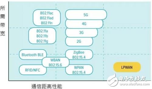
Figure 1 LPWAN compared to other wireless networks
In summary, LPWAN has the following characteristics:
Two-way communication, there is a response
Star topology (in general, no repeaters are used, and Mesh networking is not used for simplicity)
Low data rate
low cost
Very long battery life
Long communication distance
Suitable applications for LPWAN:
IoT, M2M
automated industry
Low-power applications
Battery powered sensor
Smart city, smart agriculture, meter reading, street light control, etc.
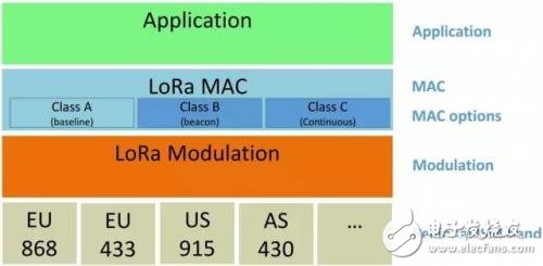
LoraWAN's relationship with LoraAlso because the names are similar, many people confuse LoRaWAN with LoRa. In fact, LoRaWAN refers to the networking protocol of the MAC layer. LoRa is just a protocol for the physical layer. Although the existing LoRaWAN networking basically uses LoRa as the physical layer, the LoRaWAN protocol also lists GFSK as the physical layer in some frequency bands. From the perspective of network layering, LoRaWAN can use any physical layer protocol, and LoRa can also be used as the physical layer of other networking technologies. In fact, several technologies that compete with LoRaWAN also use LoRa at the physical layer.

Figure 2 LoraWAN network layering (Lora is used in the physical layer in the figure, but it should be noted that the physical layer is independent of the MAC layer. As for the wireless band, the ISM band used in the figure, but any other band can be used from a technical point of view)
LoraWAN's main competitive technology
There are several LPWAN technologies on the market that also use LoRa as the physical layer, such as aiCast of Shenzhen Aisen Intelligent (AISenz Inc.). aiCast supports unicast, multicast and multicast, which is more complex and complete than LoRaWAN. Many applications that are not possible under LoRaWAN can therefore be implemented.
Sigfox uses slow-speed BPSK (300bps), and there are some promising applications.
NB-IoT (Narrow Band-IoT) is an IoT network based on existing mobile communication technologies in the telecommunications industry. It is characterized by the use of existing cellular communication hardware and frequency bands. Whether it is a telecom or a hardware vendor, the technology is very enthusiastic.
Key Technology Introduction to LoraThe core technology of LoRaWAN is LoRa. LoRa is a proprietary modulation technology from Semtech (acquired from the acquisition of CycleoSAS in 2012). In order to facilitate the readers who are not familiar with digital communication technology, two common modulation techniques, FSK and OOK, are introduced. The two modulation methods are chosen because:
1. These two are the simplest, most basic, and most common digital communication modulation methods.
2. Supported by LoRa on Semtech's SX127x chip, especially FSK is often used to compare performance with LoRa.
OOK
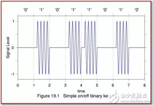
OOK is called On-Off Keying. The core idea is to use a carrier to represent a binary value (usually 1 or possibly 0), and no carrier to indicate another binary value (positive is 0, reverse is 1).

Figure 3 OOK time domain waveform
A relatively short empty carrierless interval is also inserted during the 0 and 1 switching, which can add a little redundancy to the multipath delay for the receiver to demodulate. OOK is advantageous for low-power wireless applications because only about half of the carrier is transmitted, and the carrier can be turned off for the rest of the time to save power. The disadvantage is that the noise resistance is poor.
FSK
FSK is called Frequency Shift Keying. The LoRaWAN protocol also states in some bands that (G)FSK is supported in addition to LoRa. The core idea of ​​FSK is to represent 1 and 0 with carriers of two frequencies, respectively. As long as the two frequencies are sufficiently different, the receiver can perform demodulation with a simple filter.

Figure 4 FSK time domain waveform
For the sender, the simple way is to do two frequency generators, one at Fmark and the other at Fspace. FSK modulation can be accomplished by controlling the output with 1 and 0 of the baseband signal. However, in such an implementation, the phases of the two frequency sources are usually not synchronized, resulting in discontinuities in the 0 and 1 switching, which ultimately causes additional interference to the receiver. The actual FSK system usually uses only one frequency source, and controls the frequency source to shift when 0 and 1 are switched.
GFSK is a Gaussian window before the baseband signal enters the modulation, making the frequency offset smoother. The goal is to reduce the power of the Sideband frequency to reduce interference to adjacent bands. The price is increased intersymbol interference.
Vacuum fluorescent display, referred to as VFD, is a low-energy electroluminescent display devices, the working principle and CRT similar. It has the incomparable advantage of liquid crystal display (LCD) in applications where there is a large variation in ambient brightness and no strict requirement for low power consumption, and is now widely used in audio-visual equipment, home electronics, automotive instruments, office equipment and instrumentation.
The structure of a VFD board is a typical vacuum triode structure, consisting of a cathode, a grid and an anode. In between the cathode and the anode there's a thin mesh of metal called the Grid that can be switched on or off, controlling the flow of electrons from the cathode to the anode. This VFD grid mesh is made of a thin metal plate with a thickness of 30 to 50μm, which is lithographed and made into a highly transparent fine lattice or tortoise-shaped metal mesh. When a positive voltage is applied to the grid, electrons emitted from the filament are accelerated and diffused toward the anode. When a negative voltage is applied to the grid, electron flow to the anode is cut off.
We custom VFD Grid with drawings provided by customers. The raw material we use for etched VFD Grid is SUS430 stainless steel. We are equipped with professional metal etching equipment and exposure development equipment. Our etched manufacturing capacity can achieve 0.05mm.
Vacuum Fluorescent Display Grid,VFD Grid,Custom VFD Grid,Etched VFD Grid,VFD Grid Mesh
SHAOXING HUALI ELECTRONICS CO., LTD. , https://www.cnsxhuali.com