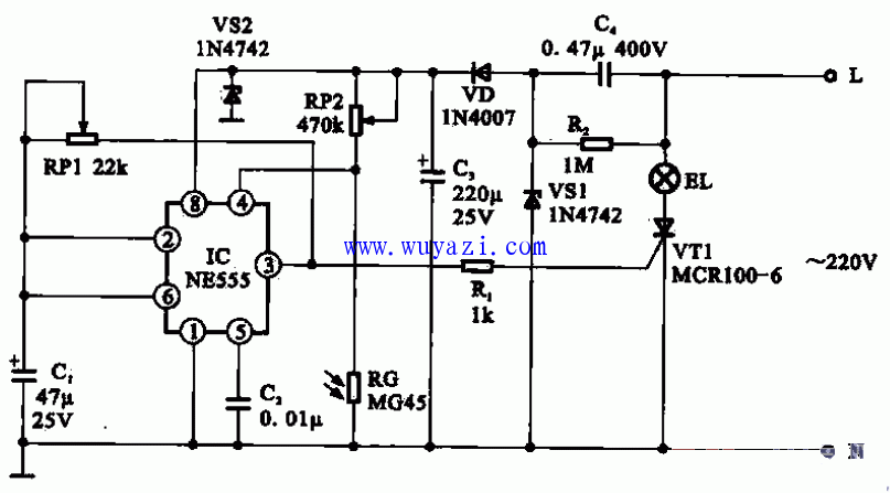
The above figure shows a nighttime warning light circuit composed of a multivibrator. The circuit is mainly composed of a photoresistor RG, a power supply circuit, a time base integrated circuit IC (NE555), a thyristor VT1 and related components.
After the circuit is powered on, the AC 220V voltage is first stepped down by cl, VD rectified, VS1, VS2 regulated, and output DC voltage of about 12V to supply power to each component in the circuit.
When the light is sufficient, the photoresistor is in a low-resistance state, the 4 pin of the integrated circuit 1C is in a low state, the lc does not work, and the warning light EL does not light.
When the brightness of the night light decreases, the resistance value of the photoresistor becomes larger, the voltage of the 4th pin of the IC rises, lC starts to work, and the oscillator circuit formed by the peripheral components starts to oscillate, so that the 3-pin output oscillating signal drives the thyristor VT1 according to The certain frequency is turned on and off, and the warning light flashes.
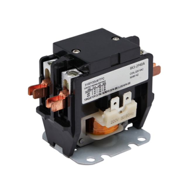
Air conditioner Contactor is mainly applicable to a line of AC 50Hz or 60Hz,rated working voltage up to 600V and rated working current up to 60A,used to close or switch off the line.The Coil Insulation is Class B(130℃),can be operated with 85% of nominal coil voltage or 110% maximum safe operate.
Air conditionar Contactors are definite purpose:AC contactor are designed for use in refrigeration,and electric heating systems.Power connections can be made with either screw terminals with quick connects or lug terminals with quick connects.

Air Conditioner AC Contactor,3 Phase AC Contactor,Electrical Air Conditioner Ac Contactor,Air Conditioner AC Magnetic Contactor
Ningbo Bond Industrial Electric Co., Ltd. , https://www.bondelectro.com