Some people are still asking me, which is the source output and the sink output of the encoder NPN and PNP output? What are the concepts of push-pull and complementary output, positive logic and negative logic, can you make it clearer? Too many sensor encoders are some of the most basic simple concepts. I thought that the automation industry was already talking about the size of the unmanned black lamp factory. The "pediatrics" of these decades ago will no longer be written by people, but because of the past experience of some major Japanese brand PLC trainers. Spreading errors, getting to the most basic concepts in the automation industry, there are still some contradictions and confusions, which trouble novices and are not easy to understand, and even choose the wrong type, resulting in no signal when connected to the site. There is too much plagiarism and patchwork on the Internet, and the contradictions between the correct and the wrong ones are mixed and continue there, causing confusion for beginners.
I remember that at an exhibition a few years ago, I went to listen to a lecture of a Japanese brand PLC. A certain trainer talked about encoders. From the error of "adding a battery is an absolute encoder, if no battery is an incremental encoder", When it comes to the opposite of the source type and the sink type, the encoder part is said to be nonsense. There is no way, that Japanese brand itself does not have an encoder, but the product promotion and training of the Japanese brand PLC has penetrated into school education, making newcomers think that what their big brands are talking about is the "right" technology, which is probably the only thing I can talk about. Let’s take a look at this PNP or NPN which is the “source†or “drain†of the muddy water.
1. NPN and PNP
NPN and PNP refer to transistor triode, P is the abbreviation of positive polarity in English, and N is negative polarity. This is a combination of two different polarities. The main function of the triode is signal amplification and switch output.
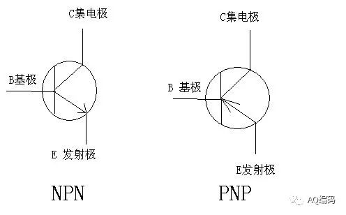
2. The particularity of NPN and PNP open-collector amplifying circuit (OC gate): the switching output of saturation amplification
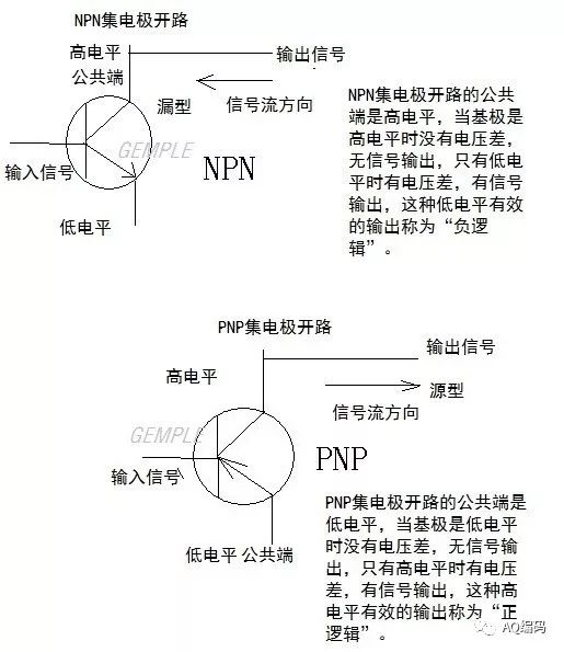
Open collector is a special application of triode amplifier circuit, C collector is set to high level, E emitter is set to low level, when B base sends a small signal, a saturated and amplified switching signal output is obtained at the collector. It is "1" in digital circuits. The open-collector amplifying circuit is sometimes referred to as an OC gate.
In the automation industry, "PNP" and "NPN" have been directly expressed as the signal output of the PNP open collector amplifier circuit and the output of the NPN open collector amplifier circuit.
The power and signal common end of the PNP type open collector is at a low level, which is also called a common cathode.
The power and signal common ends of the NPN type open collector are at a high level, which is also called a common anode.
Due to the difference in signal flow direction and the connection mode of the common terminal, the PNP signal and the NPN signal should also match the polarity of the corresponding receiving circuit, that is, the PNP receiving circuit receives the PNP signal, and the NPN receiving circuit receives the NPN signal.
Third, the source type and the drain type are the abbreviations for "source amplifying circuit" and "draining amplifying circuit", which visualize the current flow of the signal amplifier.
The open collector circuit of the triode sends a small signal, which is amplified to a switching signal and output at the collector. This is consistent with the sensor sensing a physical quantity sensing signal and then outputting a switching electrical signal, which is consistent in the circuit. Therefore, many sensors choose this type of NPN and PNP open collector output types. The pulse output of the incremental encoder is also a change of high and low pulses, so many early incremental encoders also chose this NPN and PNP open collector output type.
The source type and the sink type are a visual expression of the current flow of the PNP and NPN amplifier circuits. The abbreviation was originally introduced by the Japanese PLC. It is a way of expressing in Chinese characters in the Japanese language system. In the original Chinese school education Instead of using the abbreviated concepts of "source type" and "drain type", PNP and NPN are used instead. In the European automation products, there should not be the appearance of these two Japanese abbreviations. However, with the introduction of a large number of Japanese brand automation products, this Chinese abbreviation concept word has been brought into it. The Japanese expression and our understanding are often the opposite. Certain European brand PLCs also want to take over the economical Japanese PLC market, but they also squeeze into this chaotic team using "source" and "drain".
In the open-collector output circuit, due to the directionality of the transistor polarity, the NPN amplifier circuit, the collector signal current flows from the load end to the transmitter stage 0V, which is equivalent to this circuit as a funnel. When the output switch is turned on When the signal is sucked and flows through the funnel to 0V, when the signal is amplified, the amplified signal current flows in the opposite direction to the signal flow, which is like a funnel-shaped suction amplifier. In this understanding, the NPN amplifier circuit should be called "Sink type" amplifies and outputs.
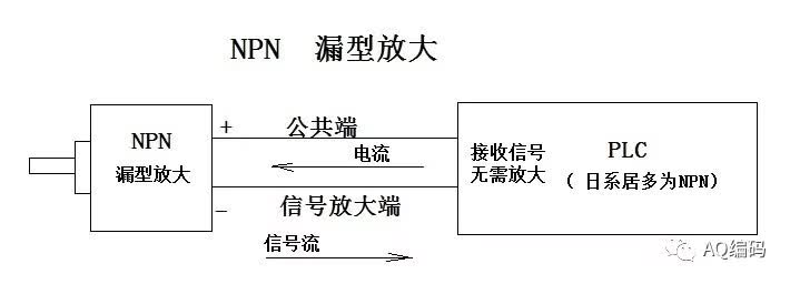
In the PNP type open collector circuit, when the signal is amplified and output, the signal current is output from the amplifier, and the amplified current is in the same direction as the signal flow, which is equivalent to the output of the active head. In this understanding, PNP amplifies The circuit is also called "source type" to amplify and output.

But from the perspective of PLC alone, there is a difference between PLC input and output. From the PLC side, the output of the signal is PLC? Or is the PLC receiving and re-amplifying the signal? In fact, the current sensor and encoder signal output has been integrated after amplification and shaping, and the PLC receiving end does not need to be amplified, so the "source" and "drain" should be judged by the sensor encoder. The Japanese PLC training is just for the convenience of self-understanding. It is to understand the signal from the PLC side. Then for the PLC to receive the encoder signal, the current flow is exactly the reverse, so that the concept of "source" and "drain" is confused. Up.
The current PLC receiver (input) can receive encoder and sensor signals without an amplifier. What kind of "source" and "drain" excitement can be gathered? Only the output of PLC will have the concept of "source" and "drain".
In fact, except for the use of Japanese PLCs, other PLCs do not need to use the abbreviations "source" and "drain", but can directly use PNP and NPN.
PNP is a low voltage as a common line, and NPN is a high voltage as a common line. As long as the wiring is correct, it seems that "source" and "drain" are okay even if the concepts are reversed. However, if the other concept "positive logic and negative logic" is also wrong, it will cause signal inversion.
Fourth, positive logic and negative logic
In the PNP type circuit, the common end of the power supply and the signal is at low level 0V. When the input is at low level, there is no voltage difference with the common end, so there is no amplified switching signal output (digital value is 0). When the input is at a high level, it forms a voltage difference with the common terminal and an amplified switch signal is output at a high level. This signal is valid at a high level (digital quantity is 1) digital mode, which is called PNP positive logic.
In the NPN circuit, the common end of the power supply and the signal is at a high level (this amplifying circuit characteristic). When the input is at a high level, there is no voltage difference between the input and output, and there is no switching signal output (digital quantity is 0) , Only when the input is low level (forming a funnel) and the output terminal forms a voltage difference and there is a switch signal output, this signal is valid at low level (digital quantity is 1) digital mode, called NPN negative logic.
5. Push-pull (HTL) output, push-pull
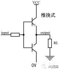
Push-pull, push-pull, push-pull, HTL
The 9-30V push-pull output is a pair of transistors, a matching combination of NPN and PNP, PNP amplified output (source signal push-out) when positive signal, and NPN amplified output (funnel signal "pulled" in) when negative signal, It is also called push-pull output (PUSH-PULL) from this, so push-pull circuits can be compatible with PNP circuits and NPN receiving circuits, depending on the connection of the common terminal. As the signal output relative to 5V is a higher level, it is also represented by HTL in European equipment.
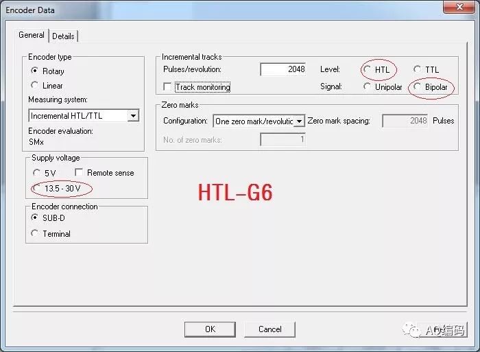
Push-pull incremental encoder with complementary output of inverted 6 channels (HTL-G6)
Complementarity is the name of a mathematical code, like in a triangle there is a 90-degree right-angle complement and a 180-degree straight line complement. In the switch logic signal, it refers to the logic complement of the switch output. When the original signal is 1, the complementary signal is 0; when the original signal is 0, the complementary signal is 1, which is the complement of the mathematical coding of the signal. In a pulse period of the incremental pulse signal, it means that the phase phase of 180 degrees is complementary to each other.
The (HTL-G6) push-pull complementary 6-channel output of the incremental encoder means that whether it is PNP connection or NPN connection (depending on the common terminal connection), the HTL-G6 signal always outputs a set of 1 and 0, A+ and A-, B+ and B-, Z+ and Z- complement each other output, such as A+ and A-, when A+ is at 1, A- is at 0; when A+ is at 0, A- is at 1.
This kind of output that contains complementary signals at the same time has no electromagnetic field disturbance to the space electromagnetic field, which is the least likely to be interfered by the space electromagnetic field. If this complementary signal is paired with twisted-pair shielded cables, the anti-interference effect will be better. , The signal can often be transmitted more than 100 meters. The push-pull complementary output HTL-G6 can also be connected to only one polarity signal output, such as NPN or PNP ABZ3 lines, or even only AB, which is also compatible and has strong anti-interference performance. HTL-G6 is compatible with PNP, NPN, push-pull, and has the best anti-interference effect. It is an ideal advanced circuit output that replaces NPN and PNP open collector output.
Pull-up resistor and optocoupler
For the NPN type signal output, it is impossible to receive the signal if it is connected to the PNP type receiving circuit (the current flow is different, the common terminal is different), then a resistor can be connected to the load end of the NPN type output, depending on the voltage across the collection resistor. Voltage change, also called voltage output. Because NPN is low-level effective, when collecting the voltage, it is converted to high-level effective (similar to PNP-type high-level effective) by changing the polarity of the collecting terminal, and the voltage is pulled up, so this resistor is commonly called "up" Pull resistance". When the signal frequency is high, the pull-up resistor responds to a delay due to the thermal resistance, which causes signal delay distortion, and the voltage to be collected during this period is also easier to be disturbed.
This usage is more like a temporary emergency and it is not recommended to use it all the time.
Optical coupler receives signals with an optical coupler. It has nothing to do with the current flow, so it can receive NPN and PNP compatible. However, the negative logic characteristic of NPN has not changed, and the signal is inverted. If it is an encoder, it will cause AB to be output in the opposite phase. The direction of rotation is reversed, and for the Z phase, it is important to note that the output is inverted. It is low at 0 o'clock, and most of it is high outside 0 o'clock.
NPN encoder, it's time to say goodbye
Transistor amplifier circuits have been used for more than half a century. As the use of sensor encoders has become more and more common, the NPN circuits commonly used in Japanese equipment have encountered a lot of troubles. The most important thing is that the use of NPN circuits must all The access is NPN consistent, the common terminal is the high level common anode of the power supply, and the current electronic control design represented by Europe is the common terminal at 0V common cathode, which causes the common cathode or the common anode of the common terminal wiring. mess. In particular, many motor system equipment now require 0V grounding, and more NPNs are connected to the large-area high-level common anode common terminal, which forms a capacitance voltage difference with the large-area 0v grounding and the shell, which changes when the device is powered on and shut down. It is easier to damage the device in an instant.
Conclusion: If NPN devices, especially NPN encoders, are mixed with European electrical equipment, the signals are more likely to be interfered, and the devices are more likely to be damaged.
On the other hand, with the large number of successful applications of HTL-6 push-pull signals containing inverted signals, the cost of this kind of compatibility and good anti-interference has been greatly reduced, which is very close to the original open-collector output cost. , It is an ideal replacement for NPN and PNP open-collector output, especially for replacing the NPN type encoder that is likely to cause confusion in the common terminal wiring. NPN encoder, it's time to say goodbye.
Electrical Insulation PVC Tape
Electrical Insulation Pvc Tape,Pvc Electrical Tape,Pvc Electrical Insulation Tape,Best Electrical Insulation Pvc Tape
Longkou Libo Insulating Material Co.,Ltd. , https://www.sdliboinsulation.com