Today, I will introduce a national invention authorized patent-a smart gas meter motor valve. The patent was applied for by Ningbo Wannuo Baotong Electromechanical Manufacturing Co., Ltd., and the authorization was announced on December 28, 2016.
Content descriptionThe utility model relates to the technical field of valves, in particular to an intelligent gas meter motor valve.
Background of the inventionSmart gas meters usually use motor valves as actuators to control the opening and closing of the gas meters. The current common smart gas meter motor valve structure mainly includes valve body, valve seat, valve cover, motor, reduction gear set, screw and sealing cover. The valve body is fixedly connected to the valve seat through the valve cover, and the motor and reduction gear set are correspondingly installed. Set in the valve seat, the top of the screw is in transmission connection with the sealing cover, the bottom end of the screw passes through the valve cover and is in transmission connection with the reduction gear set, and the top of the valve body is provided with a valve port corresponding to the sealing cover. When working, the motor drives the screw to rotate through the reduction gear set, and then drives the sealing cover to move along the axial direction of the screw, so as to achieve the effect of controlling the opening and closing of the valve port. For details, please refer to a motor valve for a gas meter disclosed by the authorized announcement number CN201339750Y.
However, the disadvantages of the above-mentioned gas meter motor valve are: First, when the sealing cover moves upward along the axial direction of the screw, negative pressure is easily generated between the sealing cover and the valve cover, so that the output torque of the motor is not enough to overcome the negative pressure force. , Resulting in the sealing cover not being able to rise, resulting in the motor valve not working properly; second, when the sealing cover is punctured, the gas easily enters the valve seat through the gap between the valve cover and the screw, which not only easily causes safety accidents, but also It is also easy to cause corrosion of the motor, which affects the service life of the motor valve; third, because the motor directly drives the seal cover to move axially through the screw, when the seal cover moves to the limit position (the highest position or the lowest position), the motor will block The phenomenon of rotation affects the service life of the motor.
Summary of the inventionThe purpose of the utility model is to aim at the defects and deficiencies of the prior art to provide an intelligent gas meter motor valve, which has a simple and reasonable structure, stable and reliable working performance, long service life, and high safety performance.
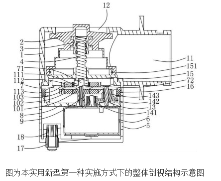
In order to achieve the above objectives, the present invention adopts the following technical solutions: the intelligent gas meter motor valve of the present invention includes a valve assembly and a motor assembly, the valve assembly is arranged above the motor assembly; the valve assembly It includes a valve body, a sealing cover, a nut and a screw. The valve body is provided with an air inlet and an air outlet respectively. The sealing cover, the nut and the screw are arranged in the valve body, and the nut and the screw The screw thread is matched, the sealing cover is arranged on the nut; the motor assembly includes a valve seat, a motor and a reduction gear set, the motor and the reduction gear are assembled in the valve seat, and the motor The shaft is in driving connection with the input end of the reduction gear set;
The valve body is fixedly connected to the valve seat, the output end of the reduction gear set is provided with a main magnetic transmission device, the bottom end of the screw is provided with a secondary magnetic transmission device, the main magnetic transmission device and the auxiliary The magnetic transmission device is magnetically coupled, and a sealing cover is provided between the valve body and the valve seat to isolate the main magnetic transmission device and the auxiliary magnetic transmission device; when the motor is working, the The reduction gear set drives the secondary magnetic transmission device to rotate through the main magnetic transmission device, and then the secondary magnetic transmission device drives the screw to rotate.
Further, a mounting seat is provided between the isolation cover and the motor, a first central shaft is provided between the isolation cover and the mounting seat, and the main magnetic transmission device includes a fixed connection from the inside to the outside. The main inner bushing, the main magnetic ring and the driven gear, the main inner bushing is sleeved on the outside of the first central shaft, and the driven gear is in driving connection with the output end of the reduction gear set; The auxiliary magnetic transmission device includes an auxiliary inner liner, an auxiliary magnetic ring, and a plastic coating, which are fixedly connected from the inside to the outside, and the auxiliary inner liner is fixedly connected with the screw.
A mounting seat is arranged between the isolation cover and the motor, a first central axis is arranged between the isolation cover and the mounting seat, and the main magnetic transmission device includes a sleeve sleeved outside the first central axis The driven gear is drivingly connected with the output end of the reduction gear set, and a number of main magnets are arranged inside the driven gear; the auxiliary magnetic transmission device includes a fixed connection with the screw The linkage plate is provided with a number of auxiliary magnets corresponding to the main magnet one-to-one inside the linkage plate.
A second central shaft is arranged between the isolation cover and the mounting seat, and the reduction gear set includes a first-stage gear arranged on the motor shaft and a second-stage gear arranged on the second central shaft A third-stage gear is fixedly connected to the second-stage gear, the first-stage gear meshes with the second-stage gear, and the third-stage gear meshes with the driven gear. The upper end surface of the isolation cover is provided with a center positioning column, and the bottom of the screw is sleeved on the outside of the center positioning column. The upper end surface of the isolation cover is provided with a ring groove for placing the auxiliary magnetic transmission device. The valve body is provided with a connecting seat sleeved outside the screw, the outer edge of the connecting seat abuts between the valve body and the isolation cover, and the upper end surface of the connecting seat is provided with a convex ring , The bottom of the sealing cover is sleeved on the outside of the convex ring. A sealing ring is matched between the valve body, the valve seat and the isolation cover. A connecting post is arranged at the bottom of the valve seat, and a sealing plug is arranged between the inner end of the connecting post and the valve seat.
The beneficial effects of the utility model are: the intelligent gas meter motor valve provided by the utility model is fixedly connected with the valve body and the valve seat, and an isolation cover is sealed between the valve body and the valve seat, so that the sealing cover and the screw are separated On the outside of the motor assembly, when the sealing cover moves upward along the axial direction of the screw, the gas in the air inlet can flow from the bottom of the sealing cover to the inside of the sealing cover, thereby preventing negative pressure inside the sealing cover and ensuring the overall valve The normal operation of the utility model makes the working performance of the utility model stable and reliable; in addition, due to the isolation cover, an independent isolation space is formed inside the motor assembly, so that gas does not flow into the interior of the motor assembly, even if the sealing cover is punctured , The gas will not enter the valve seat, which not only ensures the safety of use, but also effectively prevents the motor from being corroded by the gas and prolongs the service life; the utility model adopts a magnetic coupling transmission mode, which acts as a sealing cover When the screw is driven to the limit position, slippage will occur between the main magnetic transmission device and the auxiliary magnetic transmission device, so that the motor can drive the reduction gear set to idling, avoiding the occurrence of motor blockage, thereby protecting Up the motor.
Auto Transfer Switch,Automatic Transfer Switch,Emergency Transfer Switch,Automatic Changeover Switch
ZHEJIANG QIANNA ELECTRIC CO.,LTD , https://www.traner-elec.com