Control module circuit design
Circuit principle: The control module circuit is shown in Figure 7. K1, K2, K3, K4, each button can be sent with different address control commands by presetting the chip. For example, when the K1 trigger is set, the chip sends a B1 on command to the power line. When the button K1 is pressed, the module sends The B_ command, the switch of the corresponding lighting circuit of the receiving module with address B1 will be closed and the light will be turned on. When the K2 trigger is set, the chip sends a B1 off command to the power line. When the button K2 is pressed, the module sends a B1 off command, and the corresponding lighting circuit switch of the receiving module with the address B1 is turned on, and the light is turned off. The 10 and 1 pins of the chip are connected to the PC or MCU for communication, and the control command and the module chip setting function can be completed.
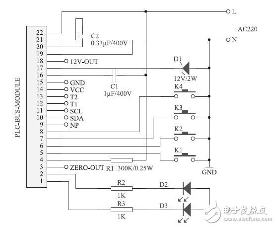
Figure 7 control module circuit
Illuminance sensor control circuit
The illuminance sensor adopts On9668, which is an optoelectronic integrated sensor that can realize adjustable light control threshold. The circuit is shown in Figure 8, Figure 9. The buttons K1, K2, K3, and K4 in the control module circuit are replaced by illuminance sensor circuits, and an illuminance sensor is connected to each of the 5, 6, 7, and 8 pins of the chip PLCBUS-9402393. When the ambient brightness reaches the setting value of the illuminance sensor Uadj, the OUT pin outputs a high level or a low level, and the OUT pin is connected to the monoflop, so that the pulse signal is output from the Q terminal and input to the PLCBUS-9402393 chip pin 5 , 6, 7, 8 end, equivalent to triggering any of the K1, K2, K3, K4 buttons of the control module circuit, can issue corresponding control commands.
Figure 8 shows the circuit that sends the trigger pulse when the ambient illuminance is greater than the set value. Figure 9 shows the circuit that sends the trigger pulse when the ambient illuminance is lower than the set value.
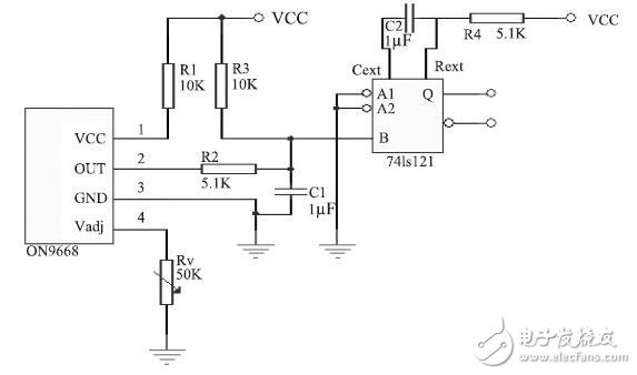
Figure 8 illuminance sensor control circuit (1)
Acrel IoT Energy Management System is a comprehensive system including the functions like real-time electricity parameters monitoring,in-time fault alarm processing and remote control of IoT devices which could support all the Acrel products connected with it.
Due to a complete devices`factory setting plan, our users could utilize the functions above once they got their IoT devices like energy meters power on without any additional adjustment through our Acrel website IoT platform and IoT APP designed for mobile phone.

Application
â— Substation
â— Building
â— Telecommunication base station
â— Industrial energy consumption
â— Operation and maintenance of power
â— Free trial
Main Function
1) HOME
It can provide device status, event list, device alarm information and energy statistics.
2) Data Monitor
3) Energy Management
â—Energy management includes energy overview and energy report.
â—Energy overview can view the electricity consumption of today, this month, and this year, and can display the corresponding same-month-on-month information, and you can also view the peak electricity consumption of today and yesterday.
â—Users and administrators can view the energy report of one or more devices.The dimensions of the report are day, week, month,quarter and year. And you can export the energy report.
4)APP
Scan the QR code of the gateway or module, connect the platform, and you can query the real-time data of the module without any other operations.
5)Demo Account
Users Name: Acrel
Password: 123456
energy management iot system,electrical iot cloud platform,iot cloud platform acrel,iot energy management system,energy management system iot
Jiangsu Acrel Electrical Manufacturing Co., LTD. , https://www.acrel.com.pk