With the expansion of colleges and universities and the rapid increase in the price of equipment and instruments, the shortage of laboratory equipment in the laboratory has become a common problem in colleges and universities. The tapping of waste equipment has become an effective way to save money and increase experimental equipment. Radar transmitters are an important part of radar teaching, but the installation of radar is limited by many conditions such as funding and venue. It is important to develop a simple and practical experimental radar transmitter.
With the upgrading of military equipment and the natural elimination of laboratory equipment, there is a large amount of waste equipment in each laboratory. Some components inside the large equipment are still relatively good, or have value in use, such as magnetrons, thyratrons, etc., although the performance parameters have decreased, but it does not affect the use, but for high-frequency devices such as waveguides The performance parameters have not changed due to good storage. In the past, these equipment (including batches of spare parts) were scrapped according to the preparation. These waste equipment and spare parts to be scrapped provide a material basis for our self-developed instruments. We have used these spare parts and spare parts to develop experimental radar transmitters. Taking the experimental radar transmitter developed as an example, we will introduce our exploration in experimental teaching.
Second, the system design of the experimental transmitter The development of the experimental transmitter has undergone several stages of selecting excellent research and development teams, drawing design, assembly and debugging, and production prototype.
According to the spare parts situation, the designed radar transmitter is shown in Figure 1. It includes power supply control module, power supply module, timer module, modulator module, magnetron oscillator module, and indicating instrument such as ammeter and voltmeter.
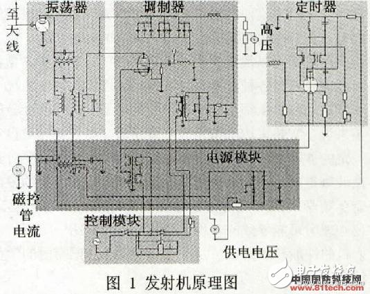
1. Assembly and commissioning According to the designed schematic diagram, look for various spare parts from the spare parts, first use a simple instrument such as a multimeter to the filaments, rectifier diodes, resistors, capacitors, etc. of various transformers, thyratrons and tubes and magnetrons. A preliminary screening was conducted. Then use a plywood as the bottom plate and assemble according to the schematic.
The electromagnetic compatibility problem is fully considered in the assembly, mainly the mutual isolation of the RF line from the intermediate frequency line and the intermediate frequency power supply. After several times of assembly after assembly, it was finally successful.
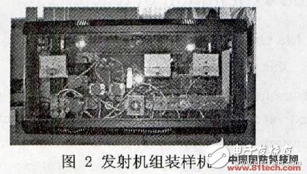
2. Production prototype and performance measurement After debugging on the plywood, the standard chassis was purchased and assembled. Due to problems such as spatial position and trace distribution, the debugging process actually went through the assembly process. After the assembly is successful, the trainees have a deeper understanding of the principle of the radar transmitter, and at the same time, the theoretical sublimation and practical skills have been improved for various disciplines such as electronic circuits, RF engineering, and mechanical engineering. The prototype of the successful assembly is shown in Figure 2.
The frequency of the microwave is high, and its wavelength can be compared with the size of the circuit system, or even shorter. At this time, the voltage and current on the transmission line are both a function of time and a function of position, so that the energy of the electromagnetic field is distributed throughout the microwave circuit. The "distribution parameters" cause the transmission of microwaves to be completely different from the ordinary radio wave band. Therefore, the measurement parameters of the microwave system are power, wavelength and standing wave parameters, which are completely different from the low frequency circuit. The measurement of the performance parameters of the transmitter prototype produced will be described later.
When the radar transmitter is used in other experiments, it also measures the performance parameters of the radar transmitter itself, which is a test of the transmitter performance.
The successful production of the radar transmitter is not only a solution to the purchase of the instrument required for the generation of the RF signal. For other experiments to be performed on the transmitter, due to various experiments that are difficult to implement on the mounted radar, The transmitter used in this experiment can be solved very well. Because of the various parameters of the transmitter, it is generally necessary to connect various waveguide components. This rigid connection is difficult in many cases on a mounted radar transmitter, and for a new student without any experience, the radar is installed. Doing microwave measurement experiments on the body has certain risks to people and equipment. However, for an independent transmitter, the microwave measurement is not limited by the space of the space, and is not limited by the connected waveguide. It also avoids the fear that the students face millions of equipment. And mysterious psychology can cause various misoperations. The following is a description of the performance parameters of the transmitter developed and the actual results of the trainees for other experiments.
1. Transmitter power, spectrum measurement
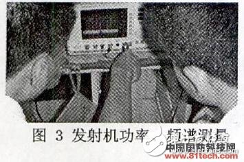
The measurement method of the transmitter power is a direct measurement by a power meter and a comprehensive measurement by a spectrum analyzer. Regardless of the method measurement, the power range that the measuring instrument can accept must first be considered. In this experiment, the spectrum analyzer integrated measurement method is used to measure the power and spectrum of the prototype. Since the spectrum analyzer can only accept 30dBmW of power, a directional coupler with a degree of attenuation of 28.7dB is connected to the precision attenuator to multiply the microwave into the spectrum analyzer. The measured power is xxW and the spectrum width is xxMHz. The measurement results are shown in Figure 3.
2. Transmitter frequency measurement
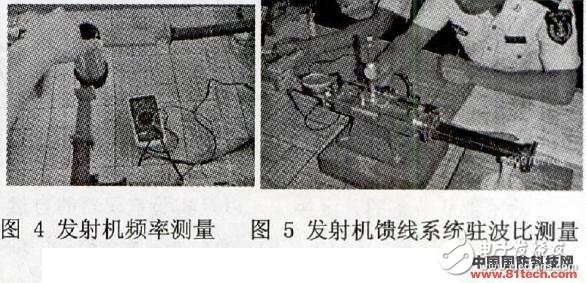
A spectrum analyzer can also be used to measure the transmitter frequency. In this experiment, a resonant cavity type direct reading frequency meter is used. The principle is that electromagnetic waves enter the cavity of the frequency meter from the waveguide through the coupling hole. When the frequency of the electromagnetic wave satisfies the resonance condition of the cavity, the absorbed energy is maximum. Correspondingly, the intensity of the electromagnetic wave signal passing through will be weakened, and the output radiance will be significantly recessed, and the frequency of the input microwave can be directly read from the surface of the casing. During the experiment, the microwave from the transmitter is attenuated by the directional coupler and connected to the direct reading frequency meter. The rotating joint is rotated and the detection current is detected by a multimeter. When the value of the detection current is maximum, the frequency reading corresponding to the frequency meter is microwave. frequency. The transmitter frequency measurement is shown in Figure 4.
3. Feeder standing wave ratio measurement
The standing wave measurement line is a precision instrument for measuring the strength and distribution of the electric field in a microwave transmission system. The structure is such that a slot is formed in the center of the wide side of the waveguide, and the metal probe extends through the slot into the waveguide. Since the probe is parallel to the electric field, the electromotive force induced by the change of the electric field on the probe becomes a current signal output through the crystal detector. The probe can move along the waveguide and the output signal shows the change in the direction of the electric field in the waveguide. Standing wave ratio is an important indicator of the feeder system. Its symbol is represented by Ï, which is defined as:
Where: Emax is the magnitude of the electric field E of the antinode and the electric field E of the Emin wave node.
The standing wave is measured as shown in Fig. 5.
4. RF signal transmission and reception experiment
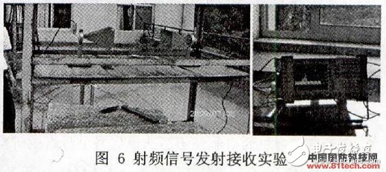
The RF signal transmission and reception experiment is to connect the microwave emitted by the transmitter to a pair of horn antennas via a coaxial cable through waveguide coaxial conversion, and then measure the frequency and power with a spectrum analyzer after receiving. The measured results are shown in Figure 6.
The use of spare parts for waste equipment to develop teaching instruments is a useful way to build university laboratories under market economy conditions. The instrument produced has the characteristics of being close to its own laboratory, simple and practical, which not only eases the contradiction of shortage of laboratory construction funds, but also explores and practices to improve the innovation ability of undergraduates, and is in line with the spirit of innovative talent cultivation.
The two selected students are seniors. They have participated in the electronic design competition in the summer. They have certain basic knowledge and experience, and have certain practical ability. However, it is necessary to develop radar transmitters for use in the microwave band. The characteristics are not in the electronic design competition, which is still challenging for them; and in the process of designing and making the transmitter, the students’ interest is stimulated through discussion, design and production with the instructors. With the potential, the innovative thinking of the students also inspired the inspiration of the faculty, so that the development work formed a virtuous circle of teacher-student interaction.
This experimental radar transmitter can be used as a teaching instrument for students to learn the principle of radar transmitter, understand the generation mechanism of radar RF signal; can be used as transmitter frequency measurement, transmitter power measurement, transmitter spectrum measurement, feeder system standing wave It is used by the supporting instruments of the measurement, radar signal receiving and other experiments to provide RF signals. The development of radar transmitters requires multi-disciplinary knowledge such as electronic circuit, radio frequency engineering, mechanical engineering, etc. The teaching and research room faculty members have learned from the radar engineering students, and finally selected two students who have participated in the electronic design competition and have excellent academic performance. Form a development team. The instructor is responsible for the guidance, and the trainees are responsible for the specific work of designing and debugging. This development team structure can be used as a comprehensive platform to stimulate the students' innovative spirit and practical ability. The successful use of the radar transmitter for this experiment can replace hundreds of thousands of radar equipments as teaching platforms to a certain extent, saving money and alleviating the shortage of instruments. At the same time, it provides preliminary exploration for exploring the cultivation of innovative talents, the exploration of experimental educational technology, the reform of experimental teaching, and the construction of laboratory for experimental asset management.
Incremental encoders provide speed, direction and relative position feedback by generating a stream of binary pulses proportional to the rotation of a motor or driven shaft. Lander offers both optical and magnetic incremental encoders in 4 mounting options: shafted with coupling, hollow-shaft, hub-shaft or bearingless. Single channel incremental encoders can measure speed which dual channel or quadrature encoders (AB) can interpret direction based on the phase relationship between the 2 channels. Indexed quadrature encoders (ABZ) are also available for homing location are startup.
Incremental Encoder,6Mm Solid Shaft Encoder,Hollow Rotary Encoder,Elevator Door Encoder
Jilin Lander Intelligent Technology Co., Ltd , https://www.jllandertech.com