This article describes common terms and definitions for digital I/O and logic analyzers.
Jitter
Jitter is the deviation from the ideal timing of the event and is usually measured based on the zero crossing of the reference signal. Jitter typically comes from crosstalk, synchronous switching outputs, and other periodically occurring interfering signals. Since jitter can vary over time, jitter measurement and quantization can be either a visual estimate in the range of seconds or a statistically based measurement, such as a statistical measurement based on the variation of the standard deviation over time.
Figure 1. Example of digital signal jitter
2. Offset
For timing (dynamic) generation, the inter-channel offset is defined as the time difference between the edges of the two data channels. For example, if both data channels are set to transition from low to high at a particular sample, the time difference between the rising edges of the two channels is the offset between the channels.
For dynamic acquisition, the inter-channel offset is defined as the difference between the sampling times of each data channel. Each time a sample point is acquired, the time for sampling each data channel is different, but the time difference between them is very small and usually falls within a certain time window. This time window is called the inter-channel offset.
The figure below shows the inter-channel skew of a set of signals.
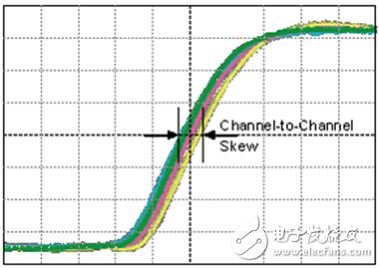
Figure 2. Example of digital signal offset
The specified inter-channel offset generally refers to the offset between all data channels on a device.
3. Rise time and fall time
The rise time (trise) is the time it takes for the signal to rise from 20% to 80% of the high level between high and low levels. The fall time (tfall) is the time it takes for the signal to go from 80% to 20% of the high level between high and low levels.
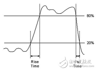
Figure 3. Digital signal rise time and fall time graph
4. Overshoot and undershoot
The pre-shoot and overshoot mainly refer to the pulse instantaneous level peak distortion of the pulse rising or falling edge (forward) or after (overshoot). Figure 4 shows an example of signal preshoot and overshoot.
Note: Overshoot, forward and undershoot are not normal.
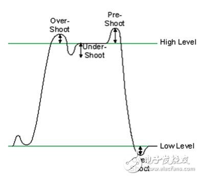
Figure 4. Digital signal overshoot, forward and undershoot
5. Stabilization time
Settling time (tS) is the time it takes for an amplifier, relay, or other circuit to reach stable operation. For signal acquisition, the settling time of the full-scale step is the time it takes for the signal to reach a certain accuracy and remain within this accuracy range.
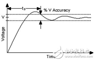
Figure 5. Stabilization time graph of digital signals
6. Duty cycle
For a clock signal, the duty cycle is the ratio of the time at which the waveform is at a logic high level to the period of the waveform. The figure below shows the difference between two waveforms with different duty cycles. Note that a 30% duty cycle waveform is at a logic high level for less than a 50% duty cycle waveform.
Figure 6. Digital signal duty cycle diagram
7. Hysteresis
Hysteresis is the difference between the voltage levels at which a signal transitions from a logic high to a logic low and from a logic low to a logic high is detected. See the hysteresis plot in Figure 7.
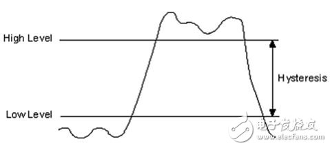
Figure 7. Hysteresis diagram of the digital signal
There is a certain degree of hysteresis in the digital inputs of all digital logic devices. The hysteresis amplitude of a particular device can be calculated by the following formula:
Hysteresis ≈ VIH - VIL
At the rising edge of the digital signal at the input, the device detects a transition from a logic low to a logic high at VIH. Conversely, when the device input voltage is below VIL, the device detects that the level of the signal changes from logic high to logic low.
Hysteresis is a very useful attribute of digital devices because it suppresses high frequency noise in digital systems to some extent. This noise is typically caused by high edge rate reflections of logic level transitions, which can cause digital devices to perform erroneous level shift detection if only one voltage threshold is used to determine a change in logic state. This phenomenon can be clearly seen in Figure 8.

Figure 8. Effect of noise on hysteresis
In the figure, the first sample point is a logic low. The second sample point is also a logic low because the signal level has not yet crossed the high threshold. The third and fourth sample points are logic high and the fifth sample point is logic low.
For devices with a fixed voltage threshold, the system's noise immunity (NIM) and hysteresis are determined by the components of the system. For example, some NI digital I/O devices allow you to control the system's NIM and hysteresis. System NIM and hysteresis can make the system have some noise immunity, but for a specific logic device, it is usually necessary to make a trade-off between the two - the greater the hysteresis, the smaller the NIM; and vice versa. If you want to set the voltage threshold correctly, you must carefully check the signal quality of the system to determine if you need higher noise immunity (higher NIM) or higher in logic level conversion. Anti-noise performance (higher hysteresis).
New Energy Battery Electrolyte And Its Additives
DADNCELL mainly produces new energy battery electrolytes for lithium batteries, high-purity crystal lithium hexafluorophosphate, lithium tetrafluoroborate, lithium perchlorate, and electrolyte additives.
Lithium Carbon Fluoride Battery Cathode Material,Lithium Silicon Alloy Chemical Material,Lithium Silicon Alloy Low Polarization,Lithium Silicon Alloy
Shandong Huachuang Times Optoelectronics Technology Co., Ltd. , https://www.dadncell.com