With the rapid development of the information system structure, the power distribution structure has also undergone earth-shaking changes. This paper mainly discusses the three aspects of power distribution structure, including: intermediate bus structure, digital control technology and new trends in the use of point-of-load power management technology.
This article refers to the address: http://
As system design engineers continue to improve converter performance and power density, traditional power conversion techniques are gradually being replaced by new power distribution structures such as the Intermediate Bus Architecture (IBA). The intermediate bus structure is a newly introduced structure that can control multiple different low voltage supply rails in a hybrid power system. Such hybrid power systems generally use ASICs, digital signal processors (DSPs), and field programmable gate arrays (FPGAs), which are commonly used in telecommunications systems, automotive electronic systems, and industrial applications.

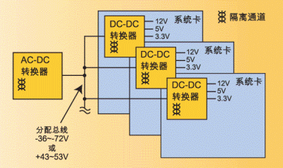
Figure 1: The traditional power distribution architecture uses isolated multi-output modular DC/DC converters, each with its own converter, but still unable to meet the increasing demands.
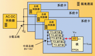
The IBA architecture uses an isolated bus converter that is powered by a high-voltage power distribution trunk and provides multiple non-isolated voltage regulators at the point of load via an "intermediate" low-voltage power distribution bus with a typical voltage between 8 volts and 14 volts. Feeding. Since the IBA architecture uses two levels of power conversion, bus converters and point-of-load regulators must be more efficient and must be smaller in size to ensure they can be mounted on smaller boards. Only the IBA architecture can be used. Give full play to its advantages and become an alternative to the superior power distribution system.
This article focuses on three aspects of the power distribution structure: for example, the advent of the intermediate bus structure; the emergence of digital control technology; and the new trend of adopting point-of-load power management technology. Each of these transitions can be seen as a new breakthrough in power distribution technology, allowing the system's lifetime and performance to be increased to unprecedented levels.
Intermediate bus structure
From a system design perspective, power management technology entered a turning point about five years ago. For desktop telecom and data communication equipment, the cooling method using fan cooling has reached the limit where the effect cannot be further broken.
Over the years, the bandwidth of communication equipment has been continuously improved, and the content of information has become more diverse, but it still cannot meet the requirements of users. The higher the user's requirements, the more digital signal processors, field-programmable gate arrays, and digital special-application integrated circuits are added to the communication equipment, so that the number of loads is increasing, and the load itself is becoming more complex, making the tradition The power distribution structure does not meet the power requirements of the new features. The conventional power distribution structure shown in Figure 1 uses isolated multi-output modular DC/DC converters (bricks), and each card has its own converter. Each load current of this structure is quite high, causing an IR drop in the PC circuit board trace between each converter brick and each load point, resulting in extremely unstable voltage.
The solution is to divide the isolation barrier, buck, and point-of-load regulation into two different conversion stages to replace the multi-output converter bricks. This structural change (see Figure 2) also has its own problems to be solved; for example, each conversion stage must occupy no more than half the space of the original solution, and the serial combination must also be able to play higher overall. s efficiency.
This structure generally uses a low-cost, low-regulation primary conversion stage to perform insulation and buck functions, while a high-efficiency, high-precision secondary conversion stage is placed near the load point. This primary conversion stage is called an intermediate bus converter (IBC). In general, the intermediate bus converter sets a constant product of "volts x seconds" for the transformer to stabilize the line voltage, but the effect of the load point regulation is generally unsatisfactory, and the voltage amplitude is generally about ±10%.
The entire voltage regulation process is usually done in the primary coil, which is responsible for monitoring the output voltage reflected by the primary coil to the auxiliary coil in turns. After the system is started, the auxiliary coil also supplies power to the primary coil control circuit, the drive circuit, and the voltage regulator circuit. In contrast, a voltage regulator at the point of load provides a very stable regulation of the load, and the voltage amplitude typically does not exceed ±1% without isolation. The primary coil power distribution bus of the telecommunications system operates over a voltage range of -36 to -72 volts, while the data communication equipment bus operates over a voltage range of +43 to 53 volts. The operating voltage of the intermediate bus is typically between 8 and 14 volts.
After such a major change in the power distribution structure, integrated circuits, voltage regulators, and modular DC/DC converters have also been rapidly developed due to their influence. Recently, the industry has been actively discussing the development of an industry standard for point-of-load regulators.
At present, the industry has established three alliance organizations (Power Distribution Open Standard Alliance (DOSA), Point of Load Alliance (POLA) and Power Supply Manufacturers Association (PSMA) on-board power supply (BMPS) program, working hard for packaging and interfaces. Develop common industry standards. This development has also led to subtle changes in the supply chain, with some suppliers starting to introduce products that are different from the previous ones. For example, semiconductor manufacturers are beginning to produce modular power converters, and power supply manufacturers have begun to design their own The silicon chip is based on this and introduces a voltage regulator in a CSP package.

Figure 2: Intermediate bus structure The size of each conversion stage must not exceed half the size of the original solution.
Digital system power supply
Digital control systems have significant advantages in terms of cost, design flexibility and reliability. This is the three main reasons for adopting digital control technology. As the process technology becomes more sophisticated and the chip size becomes smaller, the digital integrated circuit can use a smaller packageless die, so that the digital chip consumes less power than the analog chip.
In addition, digital control systems have greater noise immunity and the ability to take advantage of advanced adaptive fast control features, allowing engineers designing power supply systems to use power factor adjustment techniques and resonant switching layouts. Because these two new technologies are more complex, analog control systems have not been fully utilized. But abandoning analog control to digital control is a risky shift.
Some conservative power supply system design engineers have been using analog control systems for years, and even become obsolete because of the usual analog systems. For them, digital control is a new concept and a new tool. For example, the advance/lag compensation is changed to proportional integral derivative (PID) control. Sampling theory and time domain analysis have become common tools, and customers expect complex image user interfaces to input control coefficients and simulate the performance of power supply systems.
Digital control technology has been used mainly for some special applications. For example, the load system time constant of some applications is quite long, and there is enough time to allow the instantaneous calculation of pulse width and reference table. Therefore, digital control technology has been used mainly for this purpose. Class system. A charging system with power factor adjustment, such as a rectifier for a telephone exchange, is a good example.
Medical devices are another area where digital control technology is fully utilized. The US Food and Drug Administration (FDA) has very strict regulations on the amount of high-energy radiation a patient can withstand. The digital control system has the advantages of repeatable operation and automatic correction, so it is the preferred control solution for medical equipment.
Is the power supply system easy to manage?
As the number of loads in the power distribution structure increases and the load itself becomes more complex, system design engineers must address the management issues of the load power. Complex loads such as field-programmable gate arrays and digital signal processors require a power supply system to provide different power supplies for their cores and inputs/outputs.
According to Moore's Law, the core processor will become smaller and more precise, and usually operates at 1 volt or lower, but the input/output is subject to the communication interface standard and can only be used with conventional voltages (eg 3.3 or 5.0). Volt) operation. Since these sub-circuits are typically separated by a reverse biased electrostatic discharge diode built into the integrated circuit, the power to the integrated circuit must be supplied and terminated in a specific order, and the system must track the power supply to prevent the circuit from locking and damaging.
In addition, complex loads often require “marginal voltage regulation†when performing automated tests, and even provide information about the load conditions and their latest power consumption to high energy efficiency systems. The "Control during operation" function is one such technology. Whenever the core is powered, the supply voltage tracks its clocks to provide enough power to the core to ensure that the core can do the work in progress. Power management capabilities are the ability to flexibly configure a power supply system so that the system can take advantage of sensing numbers such as temperature, airflow or signal integrity, and automatically compensate for these sensed numbers of sensors.
If the discrete power management system occupies more and more board space, so that the footprint is close to the area of ​​the transmission system, we must use integrated power system management technology. The space on the board is invaluable, and the space used to manage the power supply system increases, which means that the space used to support the content and bandwidth of the information is compressed, so we have to adopt a more highly integrated power management system, so that we must not A common standard that supports diagnostics, built-in testing, and power system configuration is not used. Another reason why we must use an integrated power management system is that only such a system can operate at high power, maintain high stability and ensure no failure.
All in all, power management technology is not only useful, but also increasingly valued. In the end, the system can really achieve excellent performance. In many cases, it depends on the power management technology used. Therefore, the semiconductor manufacturers who know the true value of power management technology are consulting the customers at the initial stage of conceiving the power management structure. It is not required to negotiate with its customers in the final stages of the development cycle, as there is not much room for improvement at this stage. The latest developments in power distribution architecture technology fully demonstrate the close relationship between manufacturers and customers. In other words, the sooner the two parties cooperate, the more the new technology can meet the current and long-term requirements of customers.
Multi Conductor Terminal Blocks
The space-saving design and most optimized wiring are two major characteristics of JST Spring-cage Connection Terminal Blocks.The front Wiring method saves the space between two trunking.
Connect conductors that are vibration resistant,gas-tight,and have long-term stability-with the spring-loaded conductor contacting.Two potentials can be routed in parallel through a terminal point in the double function shaft,Accessories can be used to test and identify.
Supplying wiring cross section: 1.5mm²,2.5mm²,4mm²,6mm²,10mm²and16mm².
Multi Spring Terminal Block,4 Conductor Terminal Blocks,Spring Levels Terminal Blocks,Twin Terminal Blocks
Wonke Electric CO.,Ltd. , https://www.wkdq-electric.com