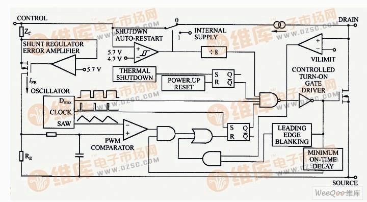
Taking the TOP intelligent power switch as an example, the picture shows the block diagram of the TOP22X series devices. The TOP22X switch has only three leads, in addition to the drain and source leads of the power switch, there is also a feedback control lead. The operating frequency is 100 kHz and the operating mode is voltage type PWM. The output voltage is injected into the feedback control line after being detected, compared, and amplified. The internal RE resistor converts the current signal into a voltage signal and compares it with the triangular wave to change the pulse width to achieve PWM modulation.
The current injected into the feedback control lead is divided into two parts: one part is supplied to the TOP switch internal control circuit and the drive circuit; the other part is the PWM control circuit. The duty cycle decreases linearly as the control current increases. The change in the output voltage changes the current of the control lead and adjusts the output voltage by changing the duty cycle. The internal shunt regulator separates the error signal current from the control lead current and passes through the resistor RE to become a voltage signal into the PWM comparator.
The TOP switch of the PWM voltage type operation also has a peak current limit function for one week. Inside the TOP switch, the power MOSFET is used to turn on the resistor Rus(on) as the sense resistor. The current-limit comparator compares the on-state voltage drop across the power MOSFET on-resistance RDS(on) with the threshold voltage. When the on-state voltage is above the threshold voltage, the power MOSFF-FET is turned off to achieve peak current limiting. In the TOP switch, the current limit comparator is temperature compensated. When RDS(on) increases with increasing temperature, the limit value of the peak current is minimized and remains approximately constant.
TOP22-227 circuit schematic
The MC333×× series of MOTOROLA's parent company is also a PWM voltage type device, which also has a peak current limiting function. A measured power MOSFET is used inside the device, and a current mirror is used to detect the current in the power switch to achieve peak current shutdown. This is a lossless current sensing method.
Electronic Components Resistor
Resistor (Resistor) commonly known as resistance directly in our daily life.It is a current limiting element. When the resistance is connected to the circuit, the resistance value of the resistor is fixed, usually two pins.Fixed resistors are those whose resistances cannot be changed.Resistance variable is called potentiometer or variable resistor.The ideal resistor is linear, that is, the instantaneous current through the resistor is proportional to the applied instantaneous voltage.Variable resistor for partial pressure.On the exposed resistor body, one or two movable metal contacts are pressed tightly.The contact position determines the resistance between any end of the resistance body and the contact.

Electronic Components Resistor,Metal Film Resistor,Metal Oxide Film Resistor
YANGZHOU POSITIONING TECH CO., LTD , https://www.yzpstcc.com