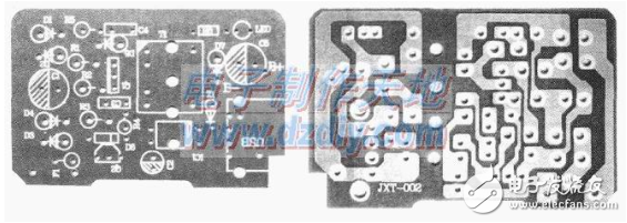
According to the circuit schematic, the single-sided PCB is designed as shown below.
When soldering the board, first prepare all the devices in Table 1. Use a multimeter to test all the times to ensure that the device is ok.
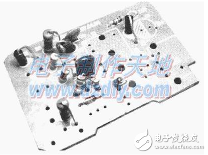
Next, soldering can be performed. The soldering is carried out according to the principle of low to high and small to large. As shown in the figure below, a small device such as a resistor or a Ceramic Capacitor is soldered to the circuit board. Then, the Electrolytic capacitor, the transformer, and the USB port are sequentially welded.
For safety reasons, use a 1/2W1Ω resistor as the fuse (F1).
Pay attention to the following points when welding:
(1) The light-emitting diode LED1 is a power indicator light, which needs to be aligned with the circular hole on the outer casing, and the pin of the LED1 can be left longer, otherwise it is not visible on the surface.
(2) Do not mix diodes D1, D5, D6, and D7. IN4007 is a low frequency diode, FR107 is a high frequency high voltage diode, and IN5819 is a low voltage high frequency diode. They cannot be substituted between them.
(3) Do not install the triodes Q1 and Q2, and do not install them.
(4) After installation and welding, carefully check each part to see if there is any solder joint.
Second, the debugging methodAfter carefully checking that the board is soldered correctly, it is necessary to enter the commissioning phase. Pay special attention to safety here, because the circuit is directly powered by 220V, and there is 22C)V high voltage on the whole circuit board. When the human body is in contact with the circuit board, electric shock will occur. So be careful in the next steps.
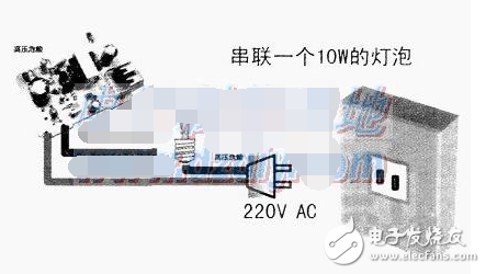
For the convenience of debugging, first solder a 220V plug wire on the PCB, and for safety, please connect a 10W bulb in series on the plug wire to prevent short circuit or wrong connection, as shown in the figure below.
Cement resistance: is the resistance wire wound on the alkali heat-resistant porcelain, coupled with heat resistant, resistant to wet outside fixed protection and corrosion resistance of the materials and the winding resistance into the square porcelain box body, using special incombustible cement packing seal.The outside of cement resistance is mainly made of ceramic materials (generally divided into high alumina porcelain and feldspar porcelain).
Cement Resistor,Thermal Cement Resistor,Thin Film Cement Resistor,Winding Cement Resistor,Fusing Cement Resistor
YANGZHOU POSITIONING TECH CO., LTD , https://www.yzpstcc.com