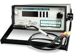
In circuits with resistors, inductors, and capacitors, the blocking effect on the current in the circuit is called impedance. The impedance is usually represented by Z. It is a complex number. It is actually called a resistor. It is called a reactance. The blocking effect of the capacitor on the alternating current in the circuit is called capacitive reactance. The inductance is a hindrance to the alternating current in the circuit. The resistance of capacitors and inductors to alternating current in the circuit is collectively referred to as reactance. The unit of impedance is ohms. The concept of impedance is not only present in the circuit, but also in the mechanical vibration system.
Electrical explanation
Impedance is a physical quantity that represents the performance of a component or the electrical performance of a segment of a circuit. The ratio of the voltage peak (or rms) Um across a passive circuit in an AC circuit to the peak (or rms) of the current through the circuit is called the impedance, expressed in z, in ohms (Ω). In the case where U is constant, the larger z is, the smaller I is, and the impedance has a limiting effect on the current. [2]
In current, the effect of an object on current obstruction is called resistance. Except for superconductors, all materials in the world have resistance, just the difference in the magnitude of the resistance. Substances with low electrical resistance are called good conductors, such as metals; materials with high electrical resistance are called insulators, such as wood and plastic. There is also a conductor between the two called a semiconductor, and a superconductor is a substance with a resistance value equal to zero, but it requires a resistivity of zero at a sufficiently low temperature and a sufficiently weak magnetic field.
In direct current and alternating current, the resistance has a hindrance to both currents; as a common component, in addition to the resistors and capacitors and inductors, the effects of both on alternating current and direct current are not as obstructive as resistors. Capacitor is "straight through", that is, it has a blocking effect on direct current, that is, direct current cannot pass, and alternating current can pass, and as the capacitance increases or the alternating current increases, the blocking effect of the capacitor on alternating current is smaller. Obstruction can be understood as "resistance", but not equivalent to resistance, which is a kind of reactance, reactance and resistance unit, collectively called "impedance". Of course, to be precise, "impedance" should have three parts, except for the two, which is "inductive resistance." Inductive reactance is the hindrance of the inductor to the current. Unlike the capacitor, the inductor has no obstructive effect on the DC power (if rigorous research, it is also hindered in the short-lived millisecond transient before the energization reaches saturation) Obstructive, the unit of inductive reactance and the unit of capacitive reactance and resistance are the same ohms.
Mechanical interpretation
The concept of impedance, resistance, and resistance is not only present in the circuit. In the vibration system, the impedance is also represented by Z. It is a complex number and is also a phasor (Phasor) containing Magnitude and Phase/Polarity. It consists of Resistance and Reactance. Resistance is the consumption of energy, and resistance is the preservation of energy. In a vibration system, the resistance generated by mass is a mass resistance, and the resistance generated by stiffness is a stiffness resistance.

Impedance matching The internal resistance of the signal source is equal to the characteristic impedance of the connected transmission line and the phase is the same, or the characteristic impedance of the transmission line is equal to the magnitude of the connected load impedance and the phase is the same, respectively called the input or output of the transmission line. Impedance matching state, referred to as impedance matching. Otherwise, it is called impedance mismatch. Sometimes it's called a match or a mismatch.
The specific relationship between the load impedance and the impedance within the signal during signal transmission. A relationship between the output impedance of a piece of equipment and the connected load impedance, so as to avoid a significant impact on the working state of the equipment itself after the load is connected. For the interconnection of electronic equipment, for example, the signal source is connected to the amplifier, and the front stage is connected to the subsequent stage. As long as the input impedance of the latter stage is greater than 5-10 times of the output impedance of the previous stage, the impedance matching is considered good; for the amplifier connection For the speaker, the tube machine should use a speaker that is equal or close to the nominal impedance of the output, and the transistor amplifier does not have this limitation, and can be connected to any impedance speaker.
When the input impedance matches, the transmission line obtains the maximum power; in the case of impedance matching at the output, only the voltage wave and the current wave traveling to the terminal on the transmission line, the carried energy is all absorbed by the load.
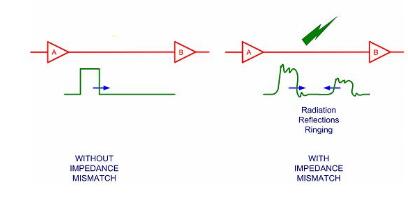
In the case of impedance mismatch, both the jet and the jet will be present on the transmission line.
From the perspective of transmission, we always try our best to avoid the phenomenon of impedance mismatch, because the appearance of reflected waves means that the power delivered to the terminal of the transmission line cannot be absorbed by the load, which reduces the transmission efficiency; In the case, the antinode of the voltage or current may damage the medium of the transmission line; and the input impedance at the beginning of the transmission line varies with the frequency, and when the multi-frequency signal is transmitted, the distortion of the machine and the line impedance is difficult to match.
The degree of impedance matching is often measured by the voltage reflection coefficient.

There are many consequences of impedance mismatch, mainly to illustrate the consequences of impedance mismatch in digital circuits.
1. The digital signal is reflected back and forth at the input of the receiving device and the output of the transmitting device. The reflected signal bounces back and forth on both sides until it is eventually completely absorbed by the resistor.
2. The reflected signal introduces a ringing signal that propagates along the trace. Ringing affects the voltage and timing of the signal and severely affects signal quality.
3. A mismatched signal path causes the signal to radiate into the environment.

Problems due to impedance mismatch can be reduced by using the terminal. The terminal is typically one or two discrete components placed near the signal line receiver. A simple example, the terminal is a low value series resistor.
The terminal suppresses the rise time of the signal and absorbs part of the reflected energy. In particular, it should be noted that the terminal does not completely eliminate the damaging effects due to impedance mismatch. But with careful selection of configuration and component values, a terminal can very effectively control the effects of signal integrity.
Not all signal lines require impedance control. Some standards, such as Compact PCI, require specific trace impedance and/or termination resistance. By developing impedance requirements, these standards are quite effective in reducing reflection, ringing, and signal line radiation.
Other standards do not have specific requirements for impedance control, leaving the designer to decide whether or not to add impedance control. The result of the decision varies from design to design, but it often depends on the length of the signal line (signal line delay Td) and the rise time of the signal (Tr). A frequently used rule is that impedance control is required when Td is greater than 1/6 of Tr.
Impedance mismatch affects the signalThere are many harmonics in the impedance mismatch signal. The concept of impedance matching is very wide, but from the perspective of harmonics, I think you want to know the concept of high-speed signal chain impedance matching, as discussed below.
1. Regardless of the frequency of the signal, the impedance matching at both ends of the transceiver will cause the next stage to receive the maximum power, which is obvious.
2. For low frequency signals, the concept of impedance matching is of little use. I personally sideways, as long as the load of the upper and lower levels are within the range of each other, no pressure, the signal will be intact, not too much.
3. For high-frequency signals, after the signal frequency increases, the high-frequency effects of various components appear, and various components begin to exhibit frequency response, and even local resonance occurs. On the one hand, the harmonics of the signal are ubiquitous, but the power is very small compared to the signal. Sometimes the frequency response of the component will have a resonance effect on a certain harmonic of the signal, thereby amplifying a part of the harmonic energy and generating a harmonic. wave. On the other hand, due to the nonlinearity of the frequency response of the components at high frequencies, this leads to the appearance of various harmonics and even harmonics. Impedance matching can make the impedance of the front and rear stages purely resistive (eliminating the influence of reactance), so that the signal can be transmitted without loss.
4. For RF and even microwave signals, the circuit signal is not lumped at all, and needs to be described by partial differential equations (and very differential equations). At this time, the size of the component will completely change the frequency response of the component, and impedance matching must be performed, because even the size of the connection will make the connection exhibit a reactance characteristic and have no different reactance characteristics. Otherwise, even in an ideal state, reflection occurs, causing various types of harmonics to appear on the signal link.
5. In summary, impedance matching is of little significance at low frequencies, but high frequency to RF is very necessary. In addition, impedance matching is an essential quality that an electronic engineer should have. Many times, even if it is unnecessary, it should be Keeping in mind in mind, this is a point of investigation in the analog part of the caller's game in recent years. At low frequencies, the concern is the transmitted waveform; at high frequencies or even at the radio frequency, the power delivered is also of concern.

Wall-hung Boiler Pressure Sensor
Boiler Water Pressure Sensor,Wall Hung Boiler Pressure Sensor,Water Pressure Transducer,Water Leak Sensor
Shenzhen Ever-smart Sensor Technology Co., LTD , https://www.fluhandy.com