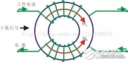
Common Mode Choke, also known as common mode inductor, is a coil that is symmetrically wound in the opposite direction and has the same number of turns on a closed magnetic ring. It is commonly used to filter electromagnetic interference of common mode, suppress electromagnetic radiation generated by high-speed signal lines from radiating outward, and improve EMC of the system. In practical applications, common mode inductance is generally added to the differential signal line.

Common mode interference
To understand the application of common mode inductance, we must first understand what is common mode interference, differential mode interference.
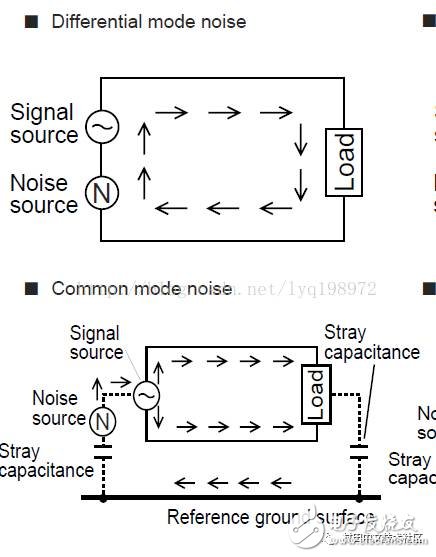
Both the common mode and the differential mode are a relative quantity. The common mode refers to the potential of the two signals A, B relative to the reference point (GND), and the differential mode refers to the relative value between A and B.
Common mode interference refers to the interference of two signal lines to the ground. If the environment produces the same-direction equal amplitude interference (superimposing the same voltage) on the ground between the two signal lines, then it is called common mode interference. Therefore, the differential signal has good common mode rejection because the differential amplifier only amplifies the difference between the two signals. If the equal-mode common mode interference can be completely eliminated, (Udiff=Ua-Ub)
Differential mode interference refers to the series mode, which is the difference between two signal lines. The differential mode interference is equivalent to adding an interference voltage between two signals, Unoise=Ua-Ub. As shown below:

Differential signal
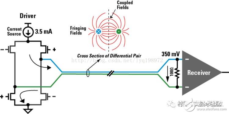
Two signals with opposite amplitudes are oscillated on the basis of a common mode voltage, which is called a differential signal. If one end is grounded, it becomes a single-ended signal. If the common mode voltage of the two signals A and B is 1.2V (LVDS), then A and B are 350mV differential modes at 1.2V. The high and low levels are determined by their difference, so it is good. To suppress common mode interference, as long as the zero point of the two signals is controlled, the logic state of the signal can be controlled. Compared with the single-ended threshold level relative to ground, it has strong anti-common mode interference capability, suitable for voltage transmission and less EMI. advantage. Why do common mode chokes are needed for differential signals because differential amplifiers have a common-mode rejection ratio that exceeds this CMRR and is distorted. The figure below is a specific implementation diagram of the difference (LVDS):

It can also be seen from the figure that since the differential signals are coupled to each other, the external EMI is also small.
Common mode inductance rejects common mode interference:
According to the right-handed screw rule, when two coils with opposite polarities on the same magnetic wrap pass two voltages of the same polarity and equal amplitude, the generated magnetic fluxes are superimposed on each other, and the inductive reactance is: Xl=wL, and the inductive reactance is large. . The magnetic flux generated by the differential signals cancel each other out.
Differential signal loop
When the local reference plane is discontinuous, the two signals can provide a loop, but the coupling strength with the ground is generally grounded.
Mietubl Global Supply Chain (Guangzhou) Co., Ltd. , https://www.mietublmachine.com