Visual navigation technology based on computer vision technology is the research focus and hotspot in the field of artificial intelligence [1]. Compared with traditional satellite positioning (GPS) navigation technology, the vision-based navigation method has the advantages of flexible implementation, high cost performance, good real-time performance, fast and accurate navigation [2-3]. However, most of the existing visual navigation systems are based on fixed-view navigation methods. These navigation systems can only be used in straight-line or small-bend driving situations. Once a large turning turn occurs, the road will deviate from the camera field of view. The path navigation line is lost and the navigation is invalid [4-5]. In order to improve the limitation of this range of viewing angles, the traditional solution is mainly to change the fixed camera to a wide-angle lens camera to increase the field of view [6], but the image distortion of the wide-angle camera is severe, and the processing accuracy and speed requirements of the image in the early stage are required. Strictly, at the same time, a large amount of image interference information is added, which increases the difficulty for subsequent image processing. In recent years, some scholars have proposed an active visual intelligent navigation method [7], which is based on the eye rotation mechanism when humans observe the road. The camera is mounted on the rotatable control pan/tilt system, and the camera focus is corrected in real time through certain feedback control. The angle with the front of the driving route ensures that the driving route is always within the camera's viewing angle. Because the method greatly expands the range of the camera's angle of view under the premise of ensuring clear viewing angle, in recent years, it has been researched and applied in the fields of target tracking [8] and face detection [6]. Among them, how to accurately obtain the navigation parameters is one of the key issues of the active visual navigation system [9]. The traditional calculation method mainly uses the high-precision calibration reference object preset, and obtains the relevant parameter value through the effective mapping relationship between the space image and the plane image. The calibration accuracy of this method is high, but the application range is limited and the calibration is complex, which is not conducive to change. Navigation of the scene [10]. In [11], a self-calculation method based on visual image is proposed. The method calculates the system parameters from the video frame image acquired by the front end, and uses the Kruppa equation and hierarchical step-by-step calibration to realize the calculation of the navigation parameters. Strong, wide range of use, but the calculation accuracy and robustness is poor, the calculation error is large in the case of background interference, and even cause navigation failure [12]. In [13], the camera is used for controllable motion, and the calculation of navigation parameters is realized by constraining the nature of motion, which improves the accuracy and robustness of parametric calculation of active visual navigation. On this basis, the rotation calculation method [14], the plane orthogonal calculation method [15] and the calculation method based on the infinity plane homography matrix [16] have been developed. This kind of method has high computational precision and good robustness, but this kind of method requires too many parameters to calculate and is computationally complex, which is difficult to apply in real-time navigation systems. On the basis of the literature [17], the computational complexity is further optimized. The relative calculation method of the two-dimensional frequency shifting motion is used to solve some parameters of the linear model, and the nonlinear optimization is introduced by the distortion method, which simplifies the calculation process effectively. However, the process of nonlinear distortion is very sensitive to the initial value and noise of the system, and the computational stability is poor.
Aiming at these problems, this paper proposes an active visual navigation parameter calculation method based on direction-guided optimization. The implementation process of the method can be roughly summarized into three steps: (1) transformation of the coordinate system. In order to achieve high-precision fitting of theoretical calculations and actual navigation systems, the transformation equations of vehicle physical coordinate system and visual image coordinate system are first given. (2) Accurate detection of the lane edge line. Accurately acquiring the lane edge line is the premise of visual navigation. In order to solve the background interference problem such as road water accumulation and shadow, based on the preliminary detection of the traditional Canny operator, the direction guidance optimization method is proposed. (3) Accurate detection of curved lines with large curvature. In order to ensure the accurate detection of lane lines in the case of large curvature turning, a generalized Hough transform method based on line and curve threshold optimization is proposed based on the previous optimization. The line segments with different curvatures are optimized and the road markings are accurately detected. And the edge line, real-time calculation and correction of the deviation angle of the navigation center guide line.
1 coordinate transformation
Coordinate transformation is the primary condition for visual navigation. In order to realize the meaning mapping between image coordinates and actual vehicle physical coordinates, this paper builds a coordinate system based on the actual road environment of the vehicle, and sets the camera center as the coordinate origin, and the X axis is the vehicle travel direction. The Y axis is the right left side of the traveling direction, and the longitudinal axis of the control pan/tilt is set to the Z axis. In order to facilitate the analysis of the subsequent PTZ control, the image acquired by the vehicle physical coordinate system is represented as (xr, yr, zr), and the corresponding pixel coordinate system can be expressed as (u, v). Figure 1 shows the coordinate transformation before and after the coordinate transformation. The relationship, the specific transformation relationship is calculated as follows [10]:

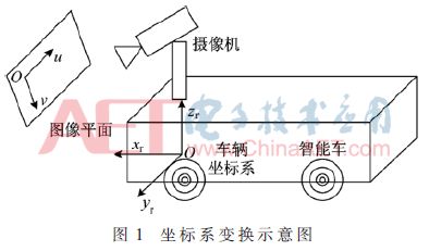
Since the road marking line to be detected during the vehicle navigation process is always in the plane state (zr=0), for the convenience of calculation, the coordinate system can be re-corrected to the xrOyr coordinate system, and the equation (1) is recalculated as:

2 Road edge detection and direction guidance optimization
2.1 Directional Guidance Optimization Implementation
Firstly, the Canny calculation is used for preliminary detection. After the image edge information is acquired, the contour information in the image is preserved, but the clutter contour information is also retained due to the interference of road features such as shadow, water accumulation and road surface crack. Therefore, the part is also retained. Directional guided search is mainly used to remove shadow interference [14]. It is assumed that the image acquired by the front end of the camera is divided into 3×3 image blocks, and the current pixel point (such as the gray center point in FIG. 2(a)) has 8 adjacent pixels. To illustrate the directionality of the search, assuming that the current pixel is in the left lane, the direction in which the vehicle travels is only three directions, as shown in Figure 2(a). Similarly, there are 3 driving directions in the right lane, as shown in Figure 2(b).
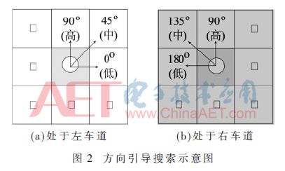
According to the driving rules of the vehicle on the road, it can be defined as the optimal selection direction is 90°, the sub-optimal selection is 45°, and the lowest level is 0°. The search process is described as taking the vehicle in the left lane as an example [15]. .
(1) Perform a plane scan with the lower left corner of the image as a reference, and if the current pixel is determined to be an edge, record and create a candidate line segment; otherwise, continue scanning until the edge point is found, and step (2) is performed.
(2) Scan according to the direction priority principle, determine the position of the edge point in three directions and record the coordinates, continue scanning until the end; if the edge points are not scanned in all three directions, then jump to step (3).
(3) Traverse the entire image and look for new edge points until the end.
After the above direction-first search is completed, a line segment set can be created and the starting coordinates of each line segment can be recorded.
2.2 Calculation of navigation parameters
On the basis of the detection of section 2.1, in order to further accurately guide the driving of the vehicle, the extraction of the navigation center guide line and the calculation of the deviation angle are performed based on the detected edge line and the road marking line. First, the method of image centroid segmentation is used to obtain an accurate navigation guide line [16], as shown in Figure 3.
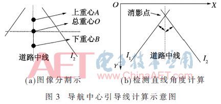
By calculating the center of gravity of the image within the two marker lines (including the image within the edge line and the marker line, mainly the boundary marker where the robot travels), the second axis is divided based on the ordinate of the center to obtain the center A of the upper and lower images. At point B, the straight line AB is the center guide line in the traveling area of ​​the robot. As shown in Fig. 3(b), O is the overall center of gravity of the frame image, and I1 and I2 are mainly used for the calculation of the off angle. The specific calculation process is shown in Figure 4.
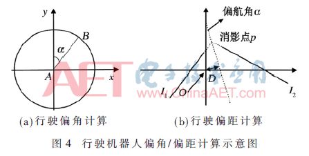
In order to calculate the deviation angle and offset of the robot, after acquiring the robot guide line, draw the circle using the coordinates and length of the end point of the line segment, and calculate the off-angle of the guide line by combining the coordinate position where the other end pixel of the line segment is located. In the experiment, the robot is first placed on the traveling section to initialize the guide line, and the road guide line is fitted with FIG. 3(a), and then the linear equation of the guide line is calculated based on FIG. 3(b), and the specific position m is determined. Taking the camera as the O point, the positional deviation D and the declination angle α of the robot are calculated based on I1 and I2.
3 experiment and result analysis
In order to verify the effectiveness of the proposed method, this part is mainly for the analysis of curved roads with complex road conditions. The video frame image size is 400 pixels × 300 pixels. Figure 5(a) shows the navigation image of the curve obtained at the experimental site of the curve test on campus, and Figure 5(b) shows the optimized test result.
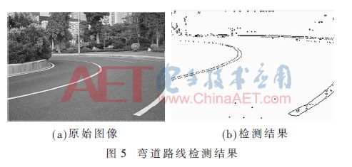
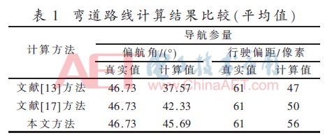
Table 1 is the average comparison result of the calculation results of the video frame sequence of the curve. It can be seen from the table that the calculation accuracy of the three methods is degraded under the curve driving situation, among which the literature [13] and the literature [17] The performance is obviously deteriorated, and the calculation accuracy of the method for this sequence still maintains a relatively high precision. The calculation error of the average yaw angle is controlled within 1.5°, and the average travel offset is controlled at about 5 pixels.
4 Conclusion
This paper focuses on the calculation method of active visual navigation system parameters, and proposes an active visual navigation parameter calculation method based on direction guidance optimization. The method is optimized and improved on the basis of the literature [13], and the calculation of the parameters is carried out by using the motion controllability of the active vision camera. After the direction guidance optimization of the traditional Canny operator detection results, the interference of clutter such as road shadow and road area water is obviously reduced. On the basis of this, the generalized Hough transform method based on threshold optimization is used to classify and optimize the detection results. Accurate detection of the inner and outer edges of the lane line and the road markings. The experimental results show that the calculation accuracy of the navigation parameters in the case of curved road driving is obviously improved, and it has excellent performance indicators.
Heavy-duty connector, also known as HDC heavy-duty connector, aviation plug, widely used in construction machinery, textile machinery, packaging and printing machinery, tobacco machinery, robot, rail transit, hot runner, power, automation and other electrical and signal connection equipment. Heavy-duty connector in structural design, material use of international advanced connector in the electrical performance of outstanding performance. The reliability of electrical connection system cannot be achieved by traditional connection method.
Hm Series Connector,Heavy Duty Connector Modular,Industrial Power Connect Modular,25Pins 5A Connector
Kunshan SVL Electric Co.,Ltd , https://www.svlelectric.com