1. The STM32 chip used in this article is STM32F103RB, and the resources used are on-chip USART1.
2, below is my circuit connection diagram: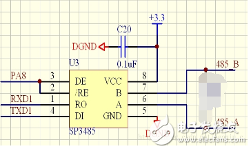
Note: The circuit can be modified slightly better. Connect the pull-down resistor to ground and pull-up resistor to 5v in B and A respectively, and select the resistance value as 10K. This is to ensure the two data lines when no data transmission is performed. The status is a determined value.
Do a simple explanation:
(1) PA8 is the transmit/receive enabler of sp3485. Sp3485 can only support half-duplex communication, so this pin is used to control whether the chip receives data or sends data.
(2) In some circuit connections, the A and B terminals of sp3485 will be connected to a pull-up resistor to 3.3V, and the other will be connected to a pull-down resistor to GND. The purpose of this is when the sp3485 does not participate in communication. Will affect the stability of the network.
3. This debugging methodPC - USB to 232 converter - RS232 / RS485 bidirectional converter - sp3485 - STM32, because it is the first time to debug sp3485 chip, so of course not much intention, first take the computer debugging, debugging pass and then look at the board Communication with the board.
4, the code of this test: main function:Int main(void)
{
/* Configure the system clocks */
RCC_ConfiguraTIon();
/* NVIC ConfiguraTIon */
NVIC_ConfiguraTIon();
/* Configure the GPIOs */
GPIO_ConfiguraTIon();
/* Configure the USART1 */
USART_Configuration();
GPIO_SetBits(GPIOA, GPIO_Pin_8); //PA8 is the sp3485 transmit/receive control terminal, which is set to send first (the function is to send a 4 and a 3 to the PC after power-on).
Delay_ms(2);//Slightly delay, the reason is to check the sp3485 manual.
USART_ClearFlag(USART1, USART_FLAG_TC); // This sentence is very important. If there is no such sentence, this 4 will be sent unsuccessfully or sent incorrectly.
/ / In fact, the manual said that the enable send bit will send a useless frame, so that frame is sent this
//The flag bit USART_FLAG_TC that was sent successfully is of course also set.
USART_SendData(USART1, 4);
While (USART_GetFlagStatus (USART1, USART_FLAG_TC) == RESET); / / clear the transmission completion flag, then you can wait for the transmission completion flag is set to determine whether the frame is finished
USART_SendData(USART1, 3);
While(USART_GetFlagStatus(USART1, USART_FLAG_TC)==RESET);
While(1)
{
GPIO_ResetBits(GPIOA, GPIO_Pin_8);//Now clear PA8, try to receive data sent by PC
Delay_ms(2);//Slightly delay, the reason is to check the sp3485 manual.
USART_ClearFlag(USART1, USART_FLAG_RXNE); // Since the send completion flag is cleared before starting to send, it is also a good habit to clear the receive completion flag.
While(1)
{
If (USART_GetFlagStatus(USART1, USART_FLAG_RXNE) == SET) / / determine whether a frame of data is received
{
Buf[j++] = USART_ReceiveData(USART1); //If the reception is complete, it will be placed directly in the cache area.
}
If(10 == j)// After the reception is completed, it will jump out and no longer receive it. If there is a meaning, it will be OK.
Break;
}
j = 0; / / clear the j variable, so that the experiment can repeatedly receive 10 data sent by the PC
GPIO_SetBits(GPIOA, GPIO_Pin_8);//Set sp3485 to send data
While(USART_GetFlagStatus(USART1, USART_FLAG_TC)==RESET);
Delay_ms(2);//Slightly delay, the reason is to check the sp3485 manual.
For(i = 0; i " 10; i++)
{
USART_SendData(USART1, buf[i]);//Send data in order
While(USART_GetFlagStatus(USART1, USART_FLAG_TC)==RESET);
}}}
Note: When using 485 communication with STM32 serial port, when sending data, it will detect that the last data transmission flag has been set, but can not immediately disable the 485 chip transmission pin, because although the flag has been Set, 485 chip data has not been completely sent out, this time requires ms level of delay, generally 2 milliseconds or so basically no problem.
RCC setting function:Void RCC_Configuration(void)
{
/* RCC system reset(for debug purpose) */
RCC_DeInit();
/* Enable HSE */
RCC_HSEConfig(RCC_HSE_ON);
/* Wait till HSE is ready */
HSEStartUpStatus = RCC_WaitForHSEStartUp();
If(HSEStartUpStatus == SUCCESS)
{
/* HCLK = SYSCLK */
RCC_HCLKConfig(RCC_SYSCLK_Div1);
/* PCLK2 = HCLK */
RCC_PCLK2Config(RCC_HCLK_Div1);
/* PCLK1 = HCLK/2 */
RCC_PCLK1Config(RCC_HCLK_Div2);
/* Flash 2 wait state */
FLASH_SetLatency(FLASH_Latency_2);
/* Enable Prefetch Buffer */
FLASH_PrefetchBufferCmd(FLASH_PrefetchBuffer_Enable);
/* PLLCLK = 8MHz * 9 = 72 MHz */
RCC_PLLConfig(RCC_PLLSource_HSE_Div1, RCC_PLLMul_9);
/* Enable PLL */
RCC_PLLCmd(ENABLE);
/* Wait till PLL is ready */
While(RCC_GetFlagStatus(RCC_FLAG_PLLRDY) == RESET)
{
}
/* Select PLL as system clock source */
RCC_SYSCLKConfig(RCC_SYSCLKSource_PLLCLK);
/* Wait till PLL is used as system clock source */
While(RCC_GetSYSCLKSource() != 0x08)
{
}}
/* Enable USART1 and GPIOA clock */
RCC_APB2PeriphClockCmd(RCC_APB2Periph_USART1 | RCC_APB2Periph_GPIOA | RCC_APB2Periph_GPIOC, ENABLE);
}
GPIO setting function:Void GPIO_Configuration(void)
{
GPIO_InitTypeDef GPIO_InitStructure;
/* Configure USART1 Tx (PA.09) as alternate function push-pull */
GPIO_InitStructure.GPIO_Pin = GPIO_Pin_9;
GPIO_InitStructure.GPIO_Mode = GPIO_Mode_AF_PP;
GPIO_InitStructure.GPIO_Speed ​​= GPIO_Speed_50MHz;
GPIO_Init(GPIOA, &GPIO_InitStructure);
/* Configure USART1 Rx (PA.10) as input floating */
GPIO_InitStructure.GPIO_Pin = GPIO_Pin_10;
GPIO_InitStructure.GPIO_Mode = GPIO_Mode_IN_FLOATING;
GPIO_Init(GPIOA, &GPIO_InitStructure);
/* Configure PC. as Output push-pull */
GPIO_InitStructure.GPIO_Pin = GPIO_Pin_8;
GPIO_InitStructure.GPIO_Mode = GPIO_Mode_Out_PP; //GPIO_Mode_Out_PP = 0x10
GPIO_InitStructure.GPIO_Speed ​​= GPIO_Speed_50MHz;
GPIO_Init(GPIOA, &GPIO_InitStructure);
GPIO_InitStructure.GPIO_Pin = GPIO_Pin_8;
GPIO_InitStructure.GPIO_Mode = GPIO_Mode_Out_PP; //GPIO_Mode_Out_PP = 0x10
GPIO_InitStructure.GPIO_Speed ​​= GPIO_Speed_50MHz;
GPIO_Init(GPIOC, &GPIO_InitStructure);
}
USART setting function:Void USART_Configuration(void)
{
USART_InitTypeDef USART_InitStructure;
USART_ClockInitTypeDef USART_ClockInitStructure;
USART_ClockInitStructure.USART_Clock = USART_Clock_Disable;
USART_ClockInitStructure.USART_CPOL = USART_CPOL_Low;
USART_ClockInitStructure.USART_CPHA = USART_CPHA_2Edge;
USART_ClockInitStructure.USART_LastBit = USART_LastBit_Disable;
/* Configure the USART1 synchronous paramters */
USART_ClockInit(USART1, &USART_ClockInitStructure);
USART_InitStructure.USART_BaudRate = 9600;
USART_InitStructure.USART_WordLength = USART_WordLength_8b;
USART_InitStructure.USART_StopBits = USART_StopBits_1;
USART_InitStructure.USART_Parity = USART_Parity_No ;
USART_InitStructure.USART_HardwareFlowControl = USART_HardwareFlowControl_None;
USART_InitStructure.USART_Mode = USART_Mode_Rx | USART_Mode_Tx;
/* Configure USART1 basic and asynchronous paramters */
USART_Init(USART1, &USART_InitStructure);
/* Enable USART1 */
USART_Cmd (USART1, ENABLE);
}
NVIC setting function:Void NVIC_Configuration(void)
{
#ifdef VECT_TAB_RAM
/* Set the Vector Table base location at 0x20000000 */
NVIC_SetVectorTable(NVIC_VectTab_RAM, 0x0);
#else /* VECT_TAB_FLASH */
/* Set the Vector Table base location at 0x08000000 */
NVIC_SetVectorTable(NVIC_VectTab_FLASH, 0x0);
#endif
}
Bitcoin mining equipment is mainly highly specialized ASIC mill , The maximum computing power of a single miner is 110T/s( Ant S19Pro mill ), The scale of computing power of the whole network is 120EH/s above . Ethereum's mining equipment is mainly graphics card mining machine , Professional ASIC Mining machines are very few , On the one hand, it is because of the of Ethereum mining algorithm [ resist ASIC sex " Improved R & D efficiency ASIC The threshold of the miner , So how much do you know about the mainstream Ethereum mining machine ?
Ethereum mining algorithm has higher requirements for memory , The purpose of this design limits ASIC The use of chips in Ethereum mining . From the results , Most Ethereum mining machines are graphics card machines , This reflects the application of Ethereum mining algorithm ASIC Success on . From the absolute value of computational power scale , The computing power of Ethereum is about 200TH/s, The computing power of bitcoin is about 120EH/s, The latter is close to the former 60 ten thousandfold .
ASIC Mining machines have high computing power , Large power consumption , Like the latest ant S19Pro mill , Rated power consumption is 3250W, Need to consume... Every day 78 Degree electricity , According to the current currency price and 0.23 The electricity price in wet season is RMB , The proportion of electricity charge is 30.68%. Other older bitcoins ASIC mill , Like ants T17 series , The proportion of electricity charges generally exceeds 50%. by comparison , The power consumption of the graphics card miner is low , The proportion of electricity is also low . such as 5600XT8 Graphics card miner of card .
Ant S19-95T It adopts aluminum alloy profile electromechanical integrated design , Parallel four fan structure . According to the measured data , In line with and better than the official data .S19 The series is provided by TSMC 7nm chip , A new generation of customized chips with perfect whole machine architecture and high conversion rate APW12 Power Supply , Reduce power loss during conversion , Use more energy-saving , Greatly shorten the return cycle of the miner . In addition, the newly upgraded mining machine operation interface is also more humanized , Real time computing power . The average computing power and the operation of each chip are clear at a glance .
Shenma mining machine M30S-86T/88T/90T, Bit micro 2020 Launched in 2013 M30S Series of new mining machines , Announced that it would M30S The series is expanded to three 3X product . stay 3X In the new standard , Bit micro promises a one-year warranty for its series of products . This series of mining machines are provided by Samsung 8nm chip , Among them, god horse M30S series , The power consumption is 38J/T, Provide higher computing power , Lower power consumption and high stability.
Ethereum Mining Machine:Jasminer X4,Bitmain Antminer E9 (2.4Gh),iPollo V1,Jasminer X4-1U,iPollo V1 Classic,
Jasminer X4-C 1U,iPollo V1 Mini SE Plus
Ethereum Mining Machine,ETHW Miner,innosilicon a10 pro,E9 Antminer,Innosilicon A11
Shenzhen YLHM Technology Co., Ltd. , https://www.ylhm-tech.com