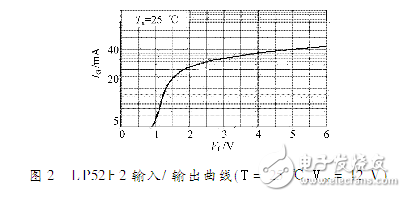
Photoelectric isolation is an important measure for anti-interference of data acquisition and control systems. Due to the nonlinearity of optocoupler devices, large-scale signal distortion will be caused by analog optical isolation. In order to improve the linearity of the opto-isolated circuit, the output current of the optocoupler device is fed back to the input terminal by a negative feedback method. Conduct static characteristics test of the photoelectric isolation circuit.
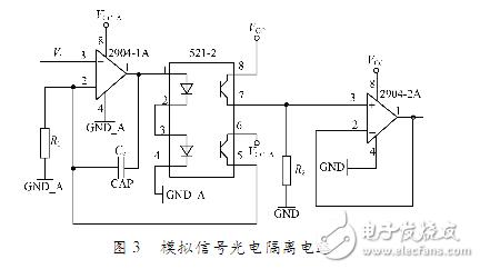
Deep negative feedback circuit design, using deep negative feedback can improve the linearity of the system. According to this principle, the optical isolation circuit of analog signal is designed here. One LP521 optocoupler and two LM2904 integrated op amps were used in the circuit. The LP521 has two optocouplers, one for signal conversion and one for negative feedback; the op amp 2904, 1A is used to form a negative feedback circuit. The op amp 2904 forms a voltage follower for increasing the load capacity of the circuit. The analog signal photoelectric isolation circuit is shown in Figure 3.


The circuit output voltage and the input voltage are linear: the LEDs of the two optocoupler channels of the LP521 are connected in series, and the current through the two diodes If1=If2. Because the two optocouplers are packaged in one device, the photoelectric characteristics are basically the same. Ideally, the collector output currents of the two optocouplers can be considered equal, that is, Ice1=Ice2.
According to the nature of the ideal op amp, the following formula can be obtained:
Vi=Ice2R1(1)
Vo=Ice1R2 (2)
So Vo=(R2/R1)Vi, the output voltage is proportional to the input voltage, and the proportionality factor is determined by R1 and R2.
Guangzhou Yunge Tianhong Electronic Technology Co., Ltd , https://www.e-cigarettesfactory.com