Oscilloscope bandwidth
For electronics engineers who often work with oscilloscopes, the bandwidth of an oscilloscope is undoubtedly one of their most important indicators. Bandwidth directly affects the fidelity of the signal and the accuracy of the measurement. What we usually call bandwidth is the -3dB bandwidth, as shown in Figure 1. Entering a 200M sine wave on a 200M bandwidth oscilloscope will theoretically reduce its amplitude by 3dB. However, if you measure the amplitude of the signal measured at this time by 0.707, you want to get the true signal amplitude, but the result is not necessarily correct. Because, in fact, when designing an oscilloscope, in order to ensure bandwidth parameters and reduce signal distortion, the attenuation of the signal in the band is usually less than 3dB. Therefore, the 200M bandwidth is a design indicator to ensure that the attenuation of the sine wave amplitude within 200M does not exceed 3 dB to provide better measurement confidence.
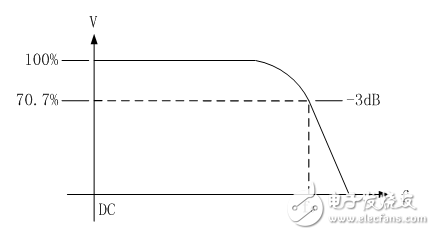
Figure 1 Bandwidth is defined as the frequency in the response curve that drops by 3dB.
Probe bandwidth
The oscilloscope must use the probe to make measurements. How does the bandwidth of the oscilloscope probe affect the oscilloscope? Below we analyze the most widely used high-impedance passive probes. High-impedance passive probes have different attenuation ratios, such as 1&TImes;, 10&TImes;, 100&TImes; etc. Even with the same probe, the bandwidth is different under different attenuation positions, so be careful when using them. For example, the bandwidth of the ZP1025S in the 1&TImes; gear is 10M, and the bandwidth in the 10x gear is 250M, as shown in Figure 2. Then, after the ZP1025S is switched to the 10× gear position and connected to the oscilloscope with the ZDS2022 bandwidth of 200M, what is the overall bandwidth of the system? The answer is: still 200M.
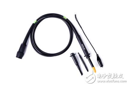
Figure 2 oscilloscope probe ZP1025S
Let's test and verify that the probe ZP1025S is connected to the ZDS2022 oscilloscope. A sine wave with a frequency of 200M and an effective value of 200mV is measured by the probe. The measurement result is shown in Figure 3. The frequency is 200M, and the effective value is 161mV, which is attenuated. About 2dB. Thus, the system consisting of a probe and an oscilloscope still has a bandwidth of 200M. It is worth noting that the signal of 200M is not as small as possible, which brings other problems.
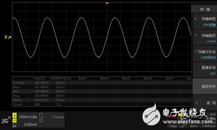
Figure 3 Actual measurement verification of 200M sine wave
The principle of the probe selection is that the bandwidth of the probe should not be lower than the bandwidth of the oscilloscope to ensure that the bandwidth of the oscilloscope can be fully utilized after connecting to the oscilloscope. When the bandwidth of the probe is lower than the bandwidth of the oscilloscope, the bandwidth of the system is limited by the probe bandwidth and may cause additional waveform distortion due to mismatch between the probe and the oscilloscope. Using the oscilloscope's recommended probes, you can avoid extra waveform distortion caused by mismatch between the probe and the oscilloscope, and ensure that the oscilloscope bandwidth extends to the probe tip when the probe bandwidth is not lower than the oscilloscope bandwidth.
Problem review
Going back to the previous question: A 200M bandwidth oscilloscope with a 200M bandwidth passive probe, can it work? Will the bandwidth be reduced to 140M? Through the above text, you should be easy to get the answer: this configuration is feasible, the bandwidth will not be reduced to 140M, but to ensure the available bandwidth of 200M, and to avoid additional waveform distortion, should use the probe recommended by the oscilloscope manufacturer as much as possible .
Some readers may still have doubts: two 200M bandwidth system cascades, why can the bandwidth still maintain 200M?
In fact, the connection of the probe to the oscilloscope is not a simple cascade.
Let us think about how the 10x attenuation of the probe is achieved. It is achieved by dividing the input impedance of the oscilloscope. If the probe is not connected to the oscilloscope, it cannot achieve 10 times attenuation. Therefore, after the probe is connected to the oscilloscope, it should be treated as a whole system, regardless of the system bandwidth or rise time. In addition, the 200M bandwidth oscilloscope, the amplitude attenuation of the 200M sine wave is actually less than 3dB, which has a certain margin. After connecting the probe, the amplitude attenuation for a sine wave within 200M still does not exceed 3dB. In order to obtain more accurate measurement results, an oscilloscope with a specified bandwidth 3 to 5 times higher than the highest frequency waveform of the signal under test should be selected based on the consideration of reducing or avoiding the frequency response characteristics of the measurement system. The impact.
The JUK universal Screw Terminal Block series has the typical features which are decisive for practical applications:
l The universal foot allows the terminal blocks to be easily snapped onto the NS35 or NS32 DIN Rail with G shape.
l Closed screw guide holes ensure screwdriver operation perfect.
l For terminal block with different wire cross-sectional areas, complete accessories are available, such as end plates, partition plates, etc.
l Potential distribution achieved by fixed bridges in the terminal center or insertion bridges in the clamping space.
l Same shape and pitch Grounding Terminal Blocks as the JUK universal series.
l Adopt ZB marker strip system,achieve unified identification.
Terminal Block Connector,Din Rail Terminal Block,Din Rail Two Layer Terminal Blocks,Two Layer Terminal Blocks
Wonke Electric CO.,Ltd. , https://www.wkdq-electric.com