According to the adjustment of the working state of the tube, we often divide the power supply into two categories: linear regulator power supply and switching regulator power supply. In addition, there is a small power supply that uses a Zener. The linear regulated power supply mentioned here refers to a direct-current regulated power supply whose regulating tube operates in a linear state. In the switching power supply, it is not the same. The switching tube is operated under both open and close conditions.
Briefly introduce the following classification: NPN regulator tube: Internal use a PNP tube to control the Darlington regulator. LDO Regulator: The regulator is a PNP. Squasi-LDO: The adjustment tube is controlled by a PNP tube to an NPN tube.
LDO (low drop output) Low Dropout Linear Regulator
The operating principle of the LDO is to adjust the Vsd voltage drop of the MOSFET by feedback so that the output voltage does not change. The output voltage ripple is small, and the current is also small. It is used for circuits with high voltage requirements such as RF modules or audio modules. It is characterized by low cost and low noise. The disadvantages are low efficiency and low output current that can only be used in buck applications. It must be noted that negative feedback must be used in order to achieve a stable loop.
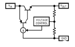
The following is the basic schematic of the LDO S-1167 Series.
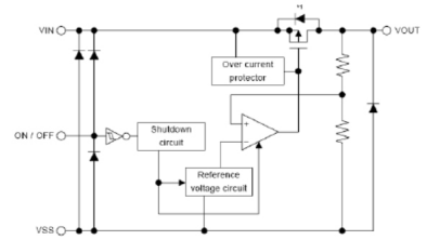
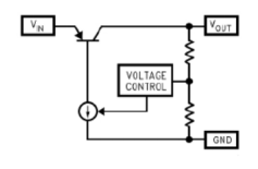
The circuit is mainly composed of a series adjustment tube, a sampling resistor, and a comparison amplifier. The sampling voltage is applied to the non-inverting input of the comparison amplifier and compared with the reference voltage Uref applied to the inverting input. After the difference between the two is amplified by the amplifier A, the voltage drop of the series adjustment tube is controlled, thereby stabilizing the output voltage. When the output voltage Uout decreases, the difference between the reference voltage and the sampling voltage increases, the drive current output from the comparison amplifier increases, and the voltage drop across the series regulator decreases, thereby increasing the output voltage. Conversely, if the output voltage Uout exceeds the desired set value, the front drive current of the comparison amplifier output decreases, thereby reducing the output voltage. During the power supply process, the output voltage correction is continuously performed, and the adjustment time is limited only by the reaction speed of the comparator amplifier and the series regulator circuit. The negative feedback in the loop always forces the voltage across the comparator's regulated input to be equal.
The efficiency of the LDO is not high. The following table shows the data obtained from the 3.3V LDO.
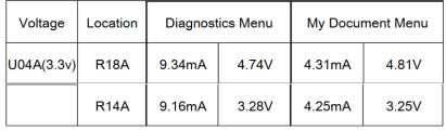
The efficiency is 67.86% under diag and 66.62% under OS. The input and output currents are basically equal because the input current to the output current pass through the PNP regulator and only consumes a little at the gate. Take the S1167B33-I6T2G as an example to measure the input and output curves as shown below:
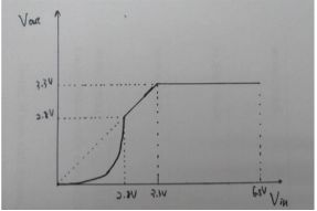
When the input is greater than 3.3V, there is a constant 3.3V output. When the input is greater than 2.8V and less than 3.3V, the input is equal to the output. When the input is less than 2.8V, the system is unstable. The output is shorted to ground and there is no large current (0.02 mA). 6.5V is defined in the spec and the input does not exceed the 6.5V measurement due to fear of damage to the device.
Another important indicator of the regulator is stability. It is often seen in our design circuit that there will be large and small capacitances at its output. What is its role? The following specific analysis of the regulator's feedback and loop stability.
Mentioned in the previous three in the regulator tube: 1.NPN regulator

For example: LM340 LM317 older 3-terminal regulator
2. LDO regulator
For example: S-1167 Series 3. Quasi-LDO Regulator
The biggest difference between the three regulators is the voltage drop and ground pin current. It is obvious that the regulators of the NPN and quasi-LDOs are slightly more complex on the adjustment tube, so the pressure drop is also greater. The Darlington's gain is very high, so only a small amount of current is needed to drive it, as is a quasi-LDO, and IGND is small. The amplification factor of the PNP tube is generally 15-20, and the IGND current of the LDO can reach 7% of the load current. The biggest benefit of the NPN regulator is that it is unconditionally stable (most do not require the addition of an external capacitor). The LDO requires a capacitor at the output to reduce the loop bandwidth and provide some positive phase compensation.
All regulators use a negative feedback loop to keep the output voltage stable. However, the feedback signal has a certain gain and phase change after passing through the loop. If the phase of the feedback signal changes by 180 degrees, negative feedback will become positive feedback, causing the output to be unstable. Therefore, the phase shift of the feedback signal through the entire loop requires a phase margin of at least 20 degrees to ensure the stability of the circuit. (The phase margin is defined as the difference between the total phase shift of the loop and -180 degrees.) The instability of the loop comes from the phase shift amount. We can inject a small sine signal through the transformer in the feedback loop, as shown in the following figure, Loop Gain =Va/Vb, incoming AC small signal from Vb, with the loop generated phase shift to reach Va. This can calculate loop gain, phase offset. (here analyzed by LDO)
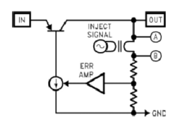
The loop gain can be measured by a network analyzer, which measures the gain response by injecting a low-level sine wave into the network loop and then sweeping from the dc signal to a frequency that reduces the gain to 0 dB.
A Bode plot is used to analyze the gain and phase changes of the feedback loop.
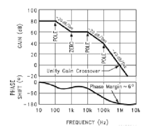
Concept: Point-zero at -20dB/10-octave change of the pole gain curve is opposite to the pole at gain and phase. Pole phase shift=-arctan(f/fp) Zero phase shift=arctan(f/fz) Assume that the DC gain is 80dB (gain at 10-100Hz), the gain from 100 to 1KHz is reduced by 20dB, and the gain from 10K to 100KHz is reduced by 20dB. The 100K-1MHz gain is reduced by 40dB (the slope has -20dB/10 frequency change). It can be seen in the figure that there are 3 POLEs and one ZERO. The gain at 1MHz is 0dB, which means that the small signal of 1MHz is cut off here. The bandwidth of this loop is 1MHz.
Can this system be stable from this Bode plot? The former said that the stability of the system mainly depends on the phase shift amount, and we only need to look at the phase shift at 0 dB (it is 1 MHz in the figure).
In the figure above, there are 3 poles and 1 zero point. The first two poles produce a phase shift of -180 degrees. The zero point produces a phase shift of 90 degrees. The last pole is at 40 dB to 0 dB with a slope of -40 dB/10. According to the pole phase shift formula -arctan(f/fp)=-arctan(10)=-1.47, the conversion angle is -84.3 degrees. So the total phase shift is -180+90-84.3=174.2 degrees. As mentioned earlier, the phase margin is equal to |-180+174.2|=5.8<20. Therefore, this loop is unstable. Looks like the above analysis is more complex, in fact, is the concept of the transfer function and the root trace diagram in the automatic control theory. Simply put, whether a (linear) system is stable (without oscillation) depends on the pole distribution of its transfer function. (The real part of the pole must be less than zero), and the greater the absolute value of the negative real part negative number, the more stable the system. We can adjust the phase margin by adding poles or zeros to stabilize the system.
To adjust the stability of the LDO system, the most common compensation method is to insert a zero point in the system to cancel the phase shift and pole. Since the LDO already requires an output capacitor for normal operation, using the output capacitor's ESR is usually the easiest and cheapest way to generate a zero. The equivalent series resistance (ESR) is a few basic characteristics that each capacitor has. Can be seen as a series equivalent circuit of resistors and capacitors. The ESR of the output capacitor creates a zero in the loop gain to reduce excessive negative phase shift. Increase the bandwidth of the system to make it more stable. Frequency at zero: Fzero = 1/(2Ï€xCoutxESR)
Assume that the cut-off frequency of an LDO system at 0 dB is 30 kHz. An output capacitor of 10uF is added at the output, and the output capacitor ESR is 1ohm. Then generate a zero at 16kHz.
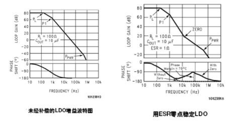
The general LDO will generate some poles by itself, such as load impedance and output capacitive reactance. There are three poles in the figure (which will not be analyzed in detail and can be scanned by the network analyzer), but there is one Ppwr in the band after 0dB, that is, outside the bandwidth. As can be seen from the comparison of the two Bode plots above, the gain curve of the second plot becomes more gradual from 80dB to 0dB when the output capacitance is increased. The system's bandwidth increases from about 40KHz to about 100KHz. The phase margin also increases accordingly (this example is not carefully calculated).
Then what are the requirements of the system for ESR? For example, if ESR=20 ohm in this example, the zero frequency will be reduced to Fzero=800Hz, which will increase the bandwidth of the system to 2MHz. From the whole Bode diagram, we find that there is one more pole Ppwr between 100K and 2MHz. This means that the system has a phase shift of -90 degrees and the zero point loses its meaning. Is ESR the smaller the better? Let ESR=50mohm. The zero frequency will drop to 320kHz. Without looking at it, we know that the stability of the system has not changed basically because the bandwidth of the system is 40KHz, and the added zero frequency of 320KHz has exceeded the bandwidth.
To compensate for LDO regulators. Therefore, the ESR requirement of the selected capacitor must be strict. First, it must meet the system's loop frequency characteristics. At the same time, it must have good temperature characteristics and cannot change too much with changes in temperature. Frequency response is also an important indicator. This tantalum capacitor is a better choice. (ESR refers to the maximum resistance at a certain frequency at a certain temperature, the manufacturer is generally defined as 25 degrees Celsius 100KHz)
ZGAR Aurora 1200 Puffs
ZGAR electronic cigarette uses high-tech R&D, food grade disposable pod device and high-quality raw material. All package designs are Original IP. Our designer team is from Hong Kong. We have very high requirements for product quality, flavors taste and packaging design. The E-liquid is imported, materials are food grade, and assembly plant is medical-grade dust-free workshops.
Our products include disposable e-cigarettes, rechargeable e-cigarettes, rechargreable disposable vape pen, and various of flavors of cigarette cartridges. From 600puffs to 5000puffs, ZGAR bar Disposable offer high-tech R&D, E-cigarette improves battery capacity, We offer various of flavors and support customization. And printing designs can be customized. We have our own professional team and competitive quotations for any OEM or ODM works.
We supply OEM rechargeable disposable vape pen,OEM disposable electronic cigarette,ODM disposable vape pen,ODM disposable electronic cigarette,OEM/ODM vape pen e-cigarette,OEM/ODM atomizer device.

Aurora 1200 Puffs,Pod System Vape,Pos Systems Touch Screen,Empty Disposable Vape Pod System,1200Puffs Pod Vape System
ZGAR INTERNATIONAL(HK)CO., LIMITED , https://www.zgarvape.com