Photocoupler
Circuit Operation Principle The telephone terminal reminder circuit consists of a power circuit, a telephone line monitoring circuit and an audible alarm circuit, as shown in Figure 3-147.
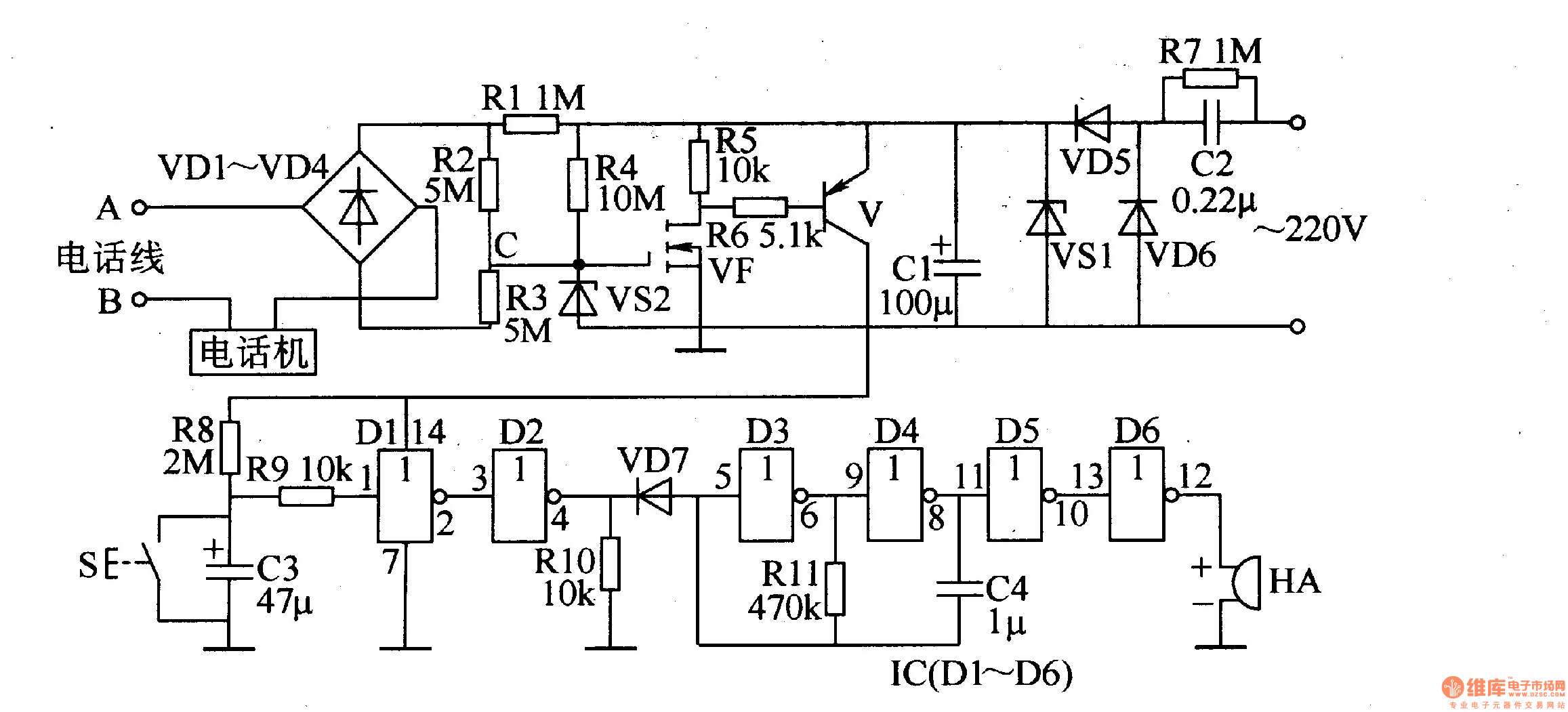
The power circuit is composed of a step-down capacitor C2, a bleeder resistor R7, a rectifier diode VD5, a VD6, a Zener diode VS1, and a filter capacitor Cl.
The telephone line monitoring circuit is composed of a rectifier diode VDl-VD4, a resistor Rl-R5, a field effect transistor VF, a transistor V, and the like.
The sound alarm circuit is composed of a buzzer HA, a six-gate (Dl-D6) integrated circuit IC and related peripheral components.
AC 220V voltage is reduced by C2, VD5 and VD6 rectification, VSl voltage regulation and Cl filtering, generating +l2V voltage, supplying VF and V.
At the end of the phone off-hook, there is a 48V voltage between the person on the telephone line and the two ends of the B. After the voltage is divided by VDl-VD4 and Rl-R3, the voltage of -16V is generated at point C, so that both VF and V are cut off. The IC does not work due to no operating voltage, and the buzzer HA is silent.
When picking up the handset, the voltage across A and B is reduced from 48V to gV, VF and V are turned on, the output voltage of the V collector is connected to the IC one by one, and the other is charged to capacitor C3 via resistor R8. Since the voltage across C3 cannot be abrupt, the 1st and 4th pins of the IC are low level, and the diode VD7 is turned on, so the oscillator (composed of the non-gate D3, the non-gate D4, the resistor R11, and the capacitor C4) stops. The buzzer HA still does not ring. When the charging of C3 is finished (about 2 minutes), the l and 4 pins of lC become high level, VD7 is turned off, the oscillator oscillates, and the buzzer HA sounds. When the phone hangs up, the voltages at both ends of A and B return to 48V, VF and V are cut off, the IC stops working, and the buzzer HA stops sounding.
At the end of the call with the other party, if the buzzer HA sounds, press the switch S to delay the call for about 2 minutes. After the call ends and the handset is lowered, if the buzzer HA sounds, it is the end of the call or the phone line is stolen.
Changing the resistance of resistor R8 and the value of C3 can change the delay time of the circuit.
Component selection
R2-R6 and R8-Rll select 1/4W carbon membrane resistor for use; Rl and R7 select 1/2W carbon membrane resistor for use.
Both Cl and C3 use aluminum electrolytic capacitors with a withstand voltage of 16V; C2 uses a polyester capacitor with a withstand voltage of 400V or a CBB non-inductive capacitor; C4 uses a monolithic capacitor.
VDl-VD7 selects 1N4007 silicon rectifier diode for use.
VSl selects l2V, l/2W Zener diode; VS2 selects l5V, l/2W Zener diode.
V selects S9015 type silicon PNP type transistor.
VF uses K2O type field effect transistor.
IC selects CD4069 type six non-gate integrated circuit.
S selects the normally open button.
HA uses FT20 buzzer.
General Purpose Servo Motors,Cnc Lathe Electric Motors,Cnc Lathe Servo Motor,Servo Motor For Sewing Machine
Zhejiang Synmot Electrical Technology Co., Ltd , https://www.synmot-electrical.com