In order to not disturb family members who have fallen asleep when watching nighttime TV sports games or literary and artistic shows, many fans or fans have installed infrared or wireless relay systems, but similar systems have power switches. It is also necessary to turn off the power of the relay system, especially for viewers watching TV in bed. In order to turn off the power, it is still a little trouble to get out of bed in a cloak. I recently made an automatic switch to solve this problem, and now I will provide it to everyone to try and improve it together. The main circuit of the whole machine is the common monolithic FM stereo broadcast transmitting integrated circuit BA1404. Its circuit is very mature. For the convenience of beginners to make their own, the coil data is also introduced: L1 and L2 are all enameled wires with a diameter of 0.3mm , Around 5 turns, coil inner diameter 3mm, length 8mm. Coil wound according to this data, the transmission frequency is about 100MHz. Within the range of ordinary FM radio. The data of other components are shown in the figure. The part of the automatic switch circuit is in the upper left of the figure. The principle is that after the TV is turned on, a strong electromagnetic field is generated around the TV. This electromagnetic field is mainly generated by the line scan system of the TV ’s kinescope. The line scan frequency is 15.625kHz in China, so it is still higher than AC mains. As long as the electromagnetic field can be detected and the power switch of the relay system is turned on, the task is completed. In order to make the circuit as simple as possible without adding too much cost, the electronic switch is served by the field effect tube VT. Because the driving power required by the field effect transistor is extremely small, the driving current is basically not required. The energy of the electromagnetic field around the TV is absorbed by the magnet coil L to turn on the TV. After D1 and D2 voltage rectification, a certain amount of electricity is accumulated on the capacitor C. When the voltage gradually increases to the turn-on voltage of the field effect tube VT (about 2V) Above), the field effect tube is turned on? The V power supply supplies power to the relay system through the current limiting resistors R and VT. This system uses a voltage of 1.5V, so the red light-emitting diode LED is used as a voltage regulator, and it can also be used as a working indicator. Selection of components: Capacitor C requires low leakage; the use of 12V voltage regulator is designed to prevent strong pulse calls and protect the field effect tube; the 10M resistor is designed to automatically broadcast the system after 10 seconds after the TV is turned off If the power supply is not used, it will be automatically cut off after a long time, which will consume more energy. The only device to be made by this machine is the magnetic bar coil L. The magnetic bar can use the medium wave magnetic bar with a diameter of 1 cm on the ordinary radio. Do not select the short wave magnetic bar. The short wave magnetic bar is lighter in color. The most important thing is the number of turns of the coil. For TVs of different sizes, the number of turns of the coil can be different. In order to ensure a successful one, or more windings, you can use the enameled wire with a diameter of 0.1mm on the magnet bar. Around 1000-1500 turns, and then use a flexible wire to weld the wire end, and then wrap it with adhesive tape, then you can connect the whole machine circuit to test the whole device. Put the magnet bar coil in an appropriate position around the TV. When the light-emitting diode LED emits light, the circuit will work normally. This position can be determined by the test. The position with the strongest electromagnetic field is about the upper back of the TV. When the number of coil turns is sufficient Many, can be placed anywhere around the TV. After the circuit works normally, pay attention to add a wire of about one meter as the antenna, and then use the FM radio to search around 100MHz. The tuning indicator lights up, indicating that there is a signal. Connect the audio output of the TV to any sound of this circuit. The input of the channel can be heard on the FM radio. When I started the experiment, I used ordinary NPN and PNP type transistors as electronic switches. The rectified voltage just cannot start the transistor circuit. Is the conduction voltage not enough? I disconnected the circuit, and the open circuit voltage could reach nearly 20V. After measuring the short-circuit current, it was found that the short-circuit current was only about 30 microamperes, and it was difficult to promote the ordinary transistor. Later, I chose the field effect transistor. The field effect tube used in this circuit is just on hand, and other similar models can be used. Figure 2 is the internal block diagram of BA1404. Finally, I have another idea: Can I use the radiant energy of the TV set to provide the relay system without using an external power supply, so that it is more convenient to use. But I have not succeeded at present. The typical power consumption of the BA1404 circuit is about 3mA. The weak energy absorbed by the magnetic bar coil cannot be achieved. Is there any other way? Readers, please give your opinion. |

Follow WeChat

Download Audiophile APP

Follow the audiophile class
related suggestion
Electronic enthusiasts provide you with the circuit diagram of the automatic switch of the dryer. There are other related resources on this site, I hope to help you.

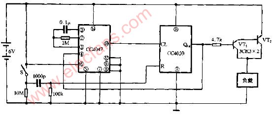
This circuit has the function of voice-activated lights with delayed lights off. The circuit is shown in Figure 197.
Power saving automatic switch circuit diagram
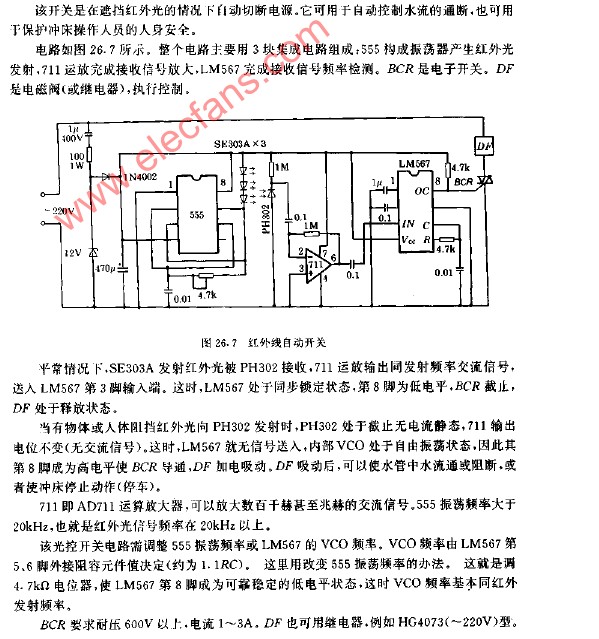
Infrared remote control automatic switch circuit diagram
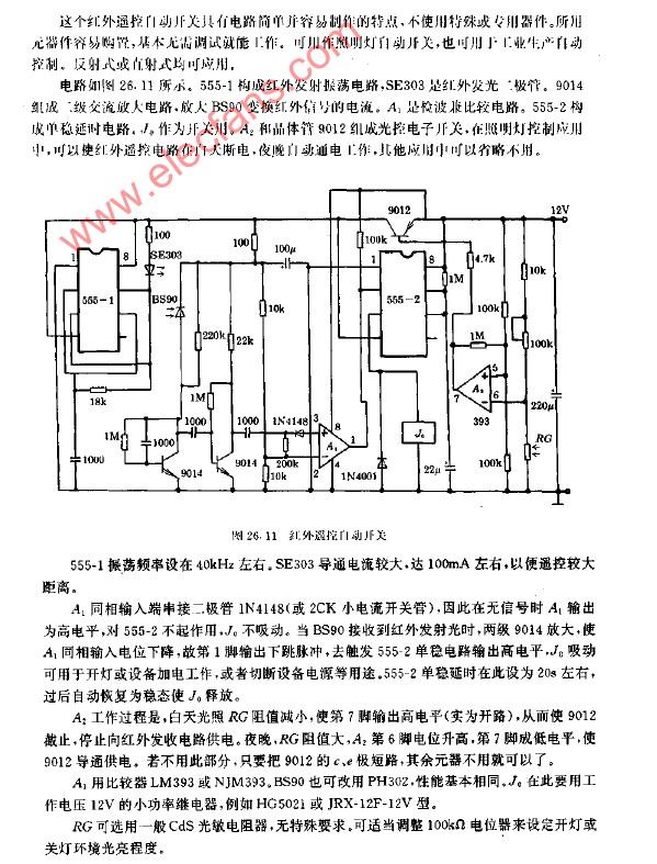
Infrared automatic switch circuit diagram
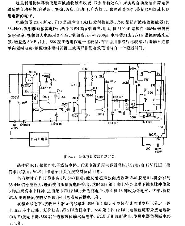
Circuit diagram of automatic switch for object movement control
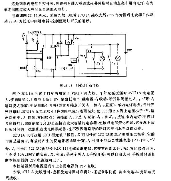
Train light automatic switch circuit diagram
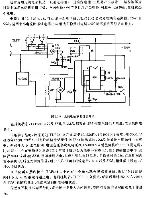
Cordless telephone power saving automatic switch
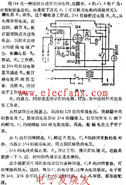
Delay automatic switch
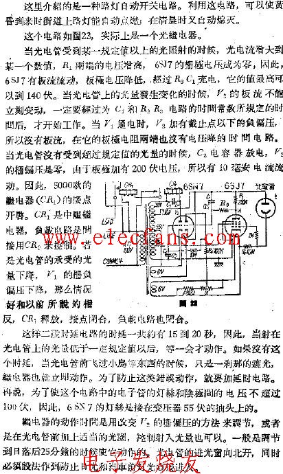
Automatic switch-photorelay circuit
What is the difference between a color TV and a black and white TV? What are the main circuits?
![[Photo] TV knowledge quiz (2)](http://i.bosscdn.com/blog/20/06/41/5132429541.gif)
