At present, the connection between the inner and outer panels of the body door cover is usually covered by a hemming process. When the punching and edging is carried out using a pass mold and a press, the edge profile of the outer panel changes according to the shape of the body, and the entire contour is wrapped. The angles are also different, and the area with a sharp transition and the area with a large angle of the edging are very difficult. At the same time, the traditional stamping edging mold occupies a large area, high cost and poor flexibility. In order to shorten the automobile development cycle and improve product competitiveness, the new internal and external board connection technology—robot piping technology is gradually being applied to the body production.
1. Robot piping technology and status quoThe robotic piping system mainly consists of three parts: the piping fixture system, the roller system, the robot and its control system. The rolling clamp system is used to fix the steel plate to be rolled on the rolling die. In the roller system, the rolling head is fixed on the industrial robot. The roller on the rolling head is selected according to the folding processing steps, and the edge of the outer steel plate is wound by the roller. The steel plate inside is bent. The robot and its control system are mainly used to control the movement track of the roller and the communication between the robot and other related systems. The program can be set according to the shape change of the body to meet the needs of the piping of different parts. When rolling, the rolling head transmits the pressure to the roller through the pressure device, and the biasing force of the workpiece is folded inward during the pressing process by the force applied by the roller, so that the outer edge of the outer plate is tightly pressed against the inner plate. The outer and inner panels are integrated into one.
Compared with the traditional stamping edging, the robot piping has a relatively low investment in mold and maintenance costs due to the small number of molds, and the development time and preparation time for putting it into use are relatively short. In addition, the piping system is extremely flexible, and different models can be produced in the same manufacturing unit. The piping robot can also perform other tasks such as gripping and gluing in the manufacturing unit. The forming precision of the rolled parts is high and the quality of the finished surface is good. Therefore, robotic piping technology has become a research hotspot in the field of plastic processing, which is benefited from the in-depth research of many scientific research institutions and large automobile manufacturers at home and abroad. Some advanced automotive manufacturers at home and abroad have applied this technology to the manufacture of external components such as doors, back covers and hoods. Other applications include sunroof openings and wheel covers.
2. Rolling robot reality application caseIn this case, the part is the engine cover, and the outer and inner plates of the part are pressed together by robot piping.
2.1 Process
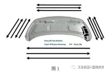
In this case, the upper and lower sides of the part adopt three-time rolling forming method, and each pressing angle is 30°, 60°, 90°, and the left and right are used. The process of four times of rolling forming is 30 in each pressing angle. °, 90°, 120°, 180°. It can be seen from the above that this case is an obvious European style.
2.2 Robot selection
When selecting a robot, it is only necessary to determine the two parameters, namely the bearing size of the robot and the working range of the robot. The working range of the robot is determined according to our process layout and simulation results. The robot bearing size depends on the process requirements, and the robot needs to capture multiple objects. How much force and robot running speed should be applied during the working process of the robot. The current rolling method requires only the calculation of the robot's rolling pressure. During the rolling process of the robot, the pressing force of the initial pressure and the final pressure is different in the same part, and the rolling pressure is different in different parts. According to the experience and the knowledge of the various rolling equipment manufacturers, the results of the robot rolling are used. The maximum seaming force is less than 200kg, so in this case, the ABB brand robot that can provide 200kg rolling pressure is selected.
2.3 Rolling press speed
This is the key parameter of the robot rolling. In general, the rolling speed of the robot is set at an average of 200mm/s. In the area where the curvature of the rolling is large and the angle of the flange is large, the speed of the robot is slower, usually 50~150mm. /s, the relative flatness, small change in curvature, and small flanging angle can be appropriately increased in the range of 200 to 300 mm/s, and the robot trajectory can be optimized to 500 mm/s.
2.4 crimping die
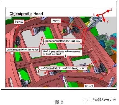
In this case, the bottoming die adopts the integral casting form, and the bottom die has the advantages of good strength, convenient assembly and debugging, and good stability. The bottom mold has high stability and wear resistance, and is surface hardened to meet the requirements of wear resistance and has high stability during heat treatment. The bottom mold uses a ductile iron material and is surface-hardened after the overall processing. The hardness is above HRC50, and the piping bottom mold is a hollow structure.
2.5 rolling head
In this case, a mechanical flexible roller is used, which is connected to the six axes of the robot. The roller is mainly composed of a robot connecting flange, a substrate, a rolling wheel set and the like.
2.6 rolling track simulation programming
The application of robotic piping press technology must master computer simulation technology. At present, the widely used simulation software in China is Robcod. Use the Robcod software to make an offline program according to the process requirements, simulate the actual working conditions, and perform pre-check interference to verify the process tempo. In the field debugging, the offline program is imported into the robot, and the debugged robot control program can be imported into the computer to find out the difference between the offline program and the online program, sum up the experience, and improve the programming level of the robot rolling.
3. Problems encountered in practical application of robotic piping technology3.1 high quality requirements for stamping parts
The height of the flange of the stamping part is generally controlled to be less than 11 mm, and it is preferable to control the height of the flange at a sharp change in the shape of the curvature. The maximum outer dimensions of the stampings and the overall dimensions of the rolled seams are not changed much, and the pressing allowance is 0~0.1mm. The inner plate of the workpiece is also required to be pressed by the robot to be pressed. The joint surface of the inner and outer plates of the workpiece requires the inner plate of the workpiece to be flat without obvious defects such as waves, pits, protrusions, etc. When the stamping parts are unstable, As a result, various edging defects are bad, which has a great impact on product quality, and also brings a large workload to the later debugging.
3.2 Robot piping production efficiency is lower than traditional hemming presses.
In this case, the robot produces a single part beat for 2 minutes and 30 seconds per roll, and the better roll speed of most tracks has been optimized to 500 mm/s, while the traditional press produces a single part with a production cycle of 30 seconds. It can be seen that if the parts with high production speed and large amount of piping are not suitable for the production method of robot piping.
3.3 Typical processing of poor piping
The two lower corners of the engine cover often have the experience of rolling wrinkles or extrusion field accumulation: (1) In the order of piping, it is recommended not to take a full roll down method, but first roll the corner and then roll the flat area. The method of pressing; (2) similar to the first method, it is also the difficulty of processing the corner first, but by adding a positioning table on the jig of the piping, correspondingly adding a matching positioning surface beside the roller of the robot arm, so that the robot arm can Use the roller to position the corner of the table first (note that it is pressed instead of rolling), and then roll around the circumference.
3.4 Common treatment of bad edges
Most of the reasons for the poor edge of the robot are due to the shortening of the outer edge of the stamping part and the smaller size of the inner plate, which causes the edge to be extruded. In the case that the stamping die cannot be repaired in a short period of time: modify the pre-enveloping angle of the robot, and adjust the angle to compensate for the dimensional changes of the flanging and inner plates of the part.
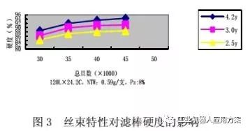
2.3 tow characteristics
In the case of ensuring the total denier of the tow or the denier of the monofilament, we separately tested the effect of the single filament denier and the total denier on the hardness of the filter rod. It was found that as the density of the monofilament increases, the hardness of the filter rod increases; moreover, the hardness of the filter rod can be increased by increasing the total denier of the tow (see Fig. 3). Therefore, we believe that the amount of plasticizer can be appropriately reduced when using a tow having a higher single denier or a higher total denier to produce a filter plug.
2.4 Filter rod placement time and environment.
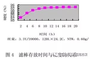
After the application of the plasticizer to the acetate filter rod, the surface of the fibers begins to soften so as to adhere to each other, and as the plasticizer penetrates into the interior of the fiber, the viscosity of the surface of the filament and the joint are reduced, a process called "cure." Due to the curing time of the plasticizer, the hardness of the filter rod increases with the increase of the standing time. The hardness of the filter rod is generally achieved after the plasticizer has cured for 2 hours. It can be seen from Fig. 4 that after the filter rod is left for 16 hours, its hardness has basically stabilized.
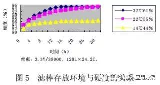
Because our area is located in the south, it has a subtropical humid climate. The annual average temperature is high and the humidity is high (average over 80%). The temperature and humidity of each season are also different. Therefore, in order to control the filter rod production workshop and storage environment more scientifically and reasonably, and to avoid the influence of environmental temperature and humidity on the filter rod, we manually simulated three test environments to measure the hardness of the filter rod under these three environmental conditions. Trend. The test results show that (see Figure 5), when the ambient temperature and humidity are moderate, the plasticizer curing time is fast, and the final hardness of the filter rod is high. When the ambient temperature and humidity are low, the hardness of the filter rod is low.
(1) The hardness of the filter rod increases as the amount of tow filling increases. Under the test conditions, the tow filling amount is preferably 0.58 to 0.68 g/piece.
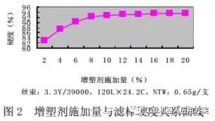
(2) The amount of plasticizer applied has a certain influence on the hardness of the filter rod. In the test range, it is more suitable to control the dosage of plasticizer at 6 to 8%. If the amount of the plasticizer applied is too large, the acetate fiber is excessively melted, and pores are formed in the cross section of the filter rod. It also causes the plasticizer to transfer to the inside of the cigarette, which affects the product's taste.
(3) The hardness of the filter rod increases as the filament denier or total denier increases.
(4) The length of storage time of the filter rod and the temperature and humidity of the storage environment also have a great influence on its hardness. Under normal circumstances, after the filter rod is placed for 2 hours, its hardness can be used. When the ambient temperature and humidity are moderate, the curing time of the plasticizer is the shortest, and the final hardness of the filter rod is high. Therefore, we require the following environment to be met: (1) The environmental control of the production workshop is in the range of T: 22 ± 2 ° C, Rh: 60 ± 5%; (2) The environmental control of the filter rod warehouse is at T: 24 ± 2 °C, Rh: 62 ± 5%; (3) Standardize the environment for filter plug inspection, T: 22 ± 2 ° C, Rh: 60 ± 5%.
Disposable Vape Puff Flex 2800 puffs is a portable Disposable Vape Pen device with 13 flavors, With 5% nic, 6ml liquid capacity and 850mah battery,Puff Flex will be your first choice Disposable vape.making it the longest-lasting disposables out in the market. Just inhale to fire up the pre-filled device.Double coil will bring the most purest tast and huger vapor on your Puff flex time.Puff flex is a quality and good taste vape with 13 flavors in stock.
Puff Flex Features:
- Disposable pod device requires no maintenance, charging, or refilling
- E-liquid: 10ml Salt Nic E-liquid per Pod Stick
- Available Nicotine: 5% 50mg
- Battery: 1500mAh
- Pre-charged, Simply puff on the device to activate
- Pre-filled, no need for messy refills
- 2800 puffs per pod, approximately equivalent to 80 cigarettes.
- Compact and Portable
Flavors:
1)Watermelon ice
2)Strawberry banana
3)Banana ice
4)Blue Razz lemonade
5)Lush ice
6)Mango ice
7)Pina colada
8)Peach ice
9)Mixed berries
10)Strawberry watermelon
11)Mamba
12)Cool mint
13)Blueberry on ice
disposable Vape pods,vape device, vape wholesale
Shenzhen Essenvape Technology Co., Ltd. , https://www.essenvape.com