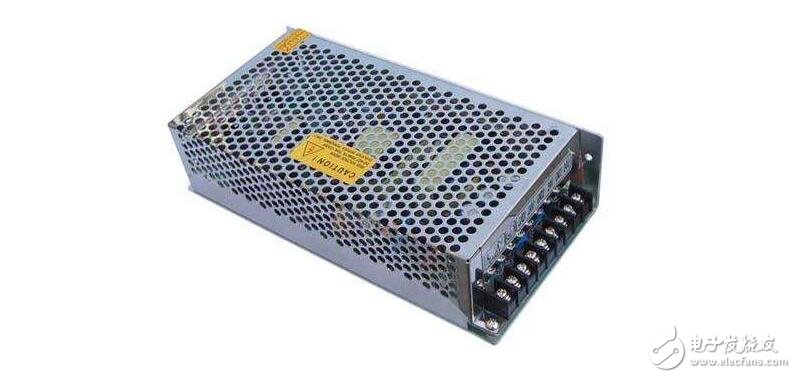
Switching power supply is a kind of power supply that uses modern power electronics technology to control the ratio of time when the switch is turned on and off, and maintains a stable output voltage. The switching power supply is generally composed of a pulse width modulation (PWM) control IC and a MOSFET. With the development and innovation of power electronics technology, switching power supply technology is constantly innovating. At present, switching power supplies are widely used in almost all electronic devices due to their small size, light weight and high efficiency. It is an indispensable power supply method for the rapid development of the electronic information industry.

Switching power supply products are widely used in industrial automation control, military equipment, scientific research equipment, LED lighting, industrial control equipment, communication equipment, power equipment, instrumentation, medical equipment, semiconductor refrigeration and heating, air purifiers, electronic refrigerators, liquid crystal displays, LED Lighting, communication equipment, audio-visual products, security monitoring, LED light bags, computer chassis, digital products and instruments.
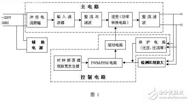
The basic components of the switching power supply:The switching power supply is composed of four parts: main circuit, control circuit, detection circuit and auxiliary power supply, as shown in Figure 1.

Main circuit
Inrush current limiting: Limits the inrush current on the input side of the power supply.
Input filter: Its function is to filter the clutter in the grid and to prevent the clutter generated by the machine from feeding back to the grid.
Rectification and filtering: directly rectify the grid AC power to a smoother DC.
Inverter: The rectified DC power is changed to high frequency AC, which is the core part of the high frequency switching power supply.
Output rectification and filtering: Provides a stable and reliable DC power supply according to the load requirements.
2. Control circuit
On the one hand, sampling from the output, comparing with the set value, then controlling the inverter, changing its pulse width or pulse frequency to make the output stable, on the other hand, according to the data provided by the test circuit, the protection circuit provides identification and provides The control circuit performs various protection measures on the power supply.
3. Detection circuit
Provides various parameters and various meter data in operation in the protection circuit.
4. Auxiliary power supply
Software (remote) startup of the power supply, power supply for protection circuits and control circuits (chips such as PWM).
Switching power supply works:The working process of the switching power supply is quite easy to understand. In the linear power supply, the power transistor is operated in a linear mode. Unlike the linear power supply, the PWM switching power supply allows the power transistor to operate in the on and off states. In the state, the volt-ampere product applied to the power transistor is small (the voltage is low and the current is large when turned on; the voltage is high and the current is small when turned off) / the voltammetric product on the power device is the power semiconductor Loss generated on the device.
Compared with linear power supplies, PWM switching power supplies work more efficiently by “chopperâ€, which is to convert the input DC voltage into a pulse voltage with an amplitude equal to the input voltage amplitude. The duty cycle of the pulse is regulated by the controller of the switching power supply. Once the input voltage is clamped into an AC square wave, its amplitude can be raised or lowered by the transformer. The voltage value of the output can be increased by increasing the number of secondary windings of the transformer. Finally, these AC waveforms are rectified and filtered to obtain a DC output voltage.
The main purpose of the controller is to keep the output voltage stable, and its operation is very similar to that of a linear controller. This means that the controller's function block, voltage reference and error amplifier can be designed to be identical to linear regulators. The difference is that the output of the error amplifier (error voltage) goes through a voltage/pulse width conversion unit before driving the power tube. Switching power supplies have two main modes of operation: forward conversion and boost conversion. Despite the small differences in the placement of the various parts, the work processes vary widely and have advantages in specific applications.

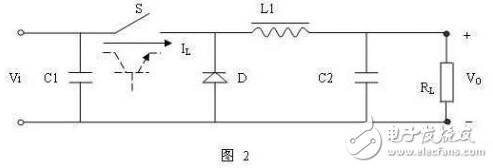
The switching power supply uses a power semiconductor device as a switching element, and the output voltage is adjusted by periodically switching the switch to control the duty ratio of the switching element. The switching element is repeatedly turned on and off at a certain time interval, and the input power source Vi supplies energy to the load RL through the switch S and the filter circuit when the switch is not turned on, and the energy storage device in the circuit when the switch S is turned off (L1, C2, circuit composed of diode D) releases the energy stored at the time when the switch is turned on to the load RL, so that the load obtains continuous and stable energy.
VO=TON/T*Vi
VO is the average voltage across the load
TON is the time each time the switch is turned on
T is the duty cycle of the switch on and off

It can be seen from the formula that changing the ratio of the switch-on time to the duty cycle, the average value of the voltage between VOs also changes. Therefore, the ratio of TON and T is automatically adjusted as the load and the input power supply voltage change, so that the output voltage VO is maintained. change. Changing the on-time TON and the duty cycle ratio, that is, changing the duty cycle of the pulse, is called "time ratio control" (TImeRaTIonControl, abbreviated as TRC).
According to the TRC control principle, there are three ways:
1. Pulse Width Modulation (PulseWithModulaTIon, abbreviated as PWM)
The switching period is constant, and the duty ratio is changed by changing the pulse width.
2. Pulse frequency modulation (PulseFrequencyModulaTIon, abbreviated as PFM)
The on-pulse width is constant, and the duty ratio is changed by changing the switching operating frequency.
3. Mixed modulation
The way in which the on-pulse width and the switching operating frequency are not fixed and can change each other is a mixture of the above two modes.
An ADSL filter separates the analogue voice-frequency signals from the ADSL (broadband) data signals(Broadband being defined as data transfer greater than 128KBPS.)
If ADSL filter/splitters are not used, the ADSL data signals are heard as "noise" on any equipment connected to the "normal" telephone-line. Apart from being annoying during a telephone conversation, there is the possibility that the additional ADSL signals may cause problems with alarm-units (etc) that may be connected across the line.
This ADSL-interference is illustrated in the diagram below that shows how the unfiltered ADSL data signals appear across the "standard" telephone equipment.
We can supply you ADSL Splitter,ADSL Filter, adsl modem splitter,telephone splitter,adsl2+ splitter,adsl filter splitter, ,adsl dsl filter splitter,adsl in line splitter,adsl filter and splitter, ,rj11 splitter, broadband splitter, mdf splitter, adsl modem filter with a good quality and best price.

ADSL Splitter, 2Wire DSL Filter, ADSL Modem Splitter, Telephone Splitter, ADSL Splitter Filter,VDSL Splitter
NINGBO YULIANG TELECOM MUNICATIONS EQUIPMENT CO.,LTD. , https://www.yltelecom.com