Light-emitting diodes (LEDs), which have long been used in consumer electronics, have recently been used in automotive lighting to provide signal functions, daytime running lights and interior lighting. With the increasing popularity of this lighting technology, manufacturers are constantly researching new applications to take full advantage of the stylish aesthetics of LED headlights and taillights.
Red LEDs are now widely used in taillights. Although cost is still a problem, factors such as safety, environmental protection and flexible styles tend to use LEDs. One of the most popular applications is the central brake light. This design concept demonstrates the use of the same LED array for taillights and brake lights.
This article refers to the address: http://
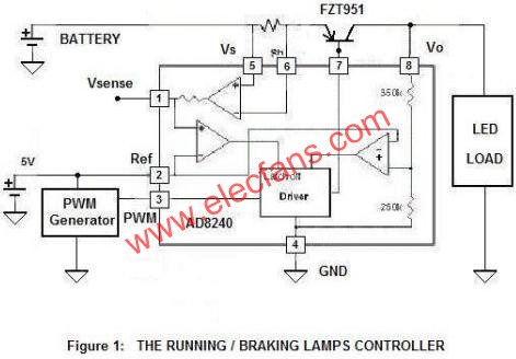
Figure 1: Drive/brake light controller
The brightness of the LED is controlled by a simple switch that dims when driving and brightens when braking. The functional block diagram is shown in Figure 1, including the LED driver/monitor AD8240, PNP adjustment tube, and PWM generator. The AD8240 provides a constant voltage to drive the LEDs. It also provides cost-effective LED light monitoring and short circuit protection. When the battery voltage is between 12.5 V and 27 V, the output is stable at 12 V.
Figure 2 shows the PWM generator, which consists of two 555 timers. The PWM signal controls the brightness of the LED. When the PWM input is high, VO is turned on; when the PWM input is low, VO is turned off. The AD8240 is designed to operate up to 500 Hz with a typical duty cycle ranging from 5% to 95%.

Figure 2: PWM Signal Generator
The AD8240 offers a low power, low cost, small package solution. The internal current sense amplifier measures the voltage across the external shunt resistor; when the current measurement falls below a preset threshold, it indicates that an LED open condition has occurred. When the current reaches the level set by the external shunt resistance value, the output voltage is locked, thereby limiting the output current. When the sense amplifier output exceeds 5 V, the internal comparator will cause the driver to lock the output voltage. The latch is reset during the next PWM cycle. Overcurrent conditions can also be detected by measuring the sense amplifier output.
Since the inductance required for the switch design is not required, the cost is further reduced; and the operating power consumption of the LED lamp is much lower than that of the incandescent lamp, so no switch driver is required.
The LED's switching depends on the digital voltage on the CMOS-compatible PWM pin (pin 3 of AD8240). For simple switching control, this voltage can be continuous; for dimming control, this voltage is PWM. The PWM frequency should be below 500 Hz and the duty cycle can range from 5% to 100%. Typical values ​​are 5% (when driving) and 95% (when braking). In Figure 2, the PWM frequency is determined by R1, R2 and C1 of timer A1. The pulse period is:
T = 0.693 (R1 + 2 R2) C1
When R1 = 49.9 kΩ, R2 = 10 kΩ, C1 = 0.1 μF, the period is 4.84 ms, or approximately 206 Hz.
Timer A2 converts this signal into a pulse width modulated signal whose duty cycle is determined by R3, R4, R5 and C2. The pulse width is determined by:
Pulse width = 1.1 RC2
Where R is equal to the shunt resistance of R5, R3, and R5 or the shunt resistance of R4 and R5, depending on the switch position. When R3 = 2.37 kΩ, R4 = 45.7 kΩ, R5 = 42.4 kΩ, C2 = 0.1 μF, the duty cycle is 5% (switch is in position 1), 50% (switch is in position 2) or 95% (switch is OFF) position).
Note that the LED brightness increases as the duty cycle increases. When the brake is pressed, the duty cycle is 95% and the LED array is the brightest. During normal driving, the duty cycle is 5% and the LED array is dimmed. Sharing an LED array in both operating states can reduce costs.
In the event of a short or overload condition, the voltage on Vsense (Pin 1) drops to 0 V and the output turns off. This circuit will be reset in the next PWM cycle. If this continues, the AD8240 will attempt to drive the output to 12 V, turning it off and restarting after each PWM cycle.
This circuit provides a way to drive and monitor LEDs with only two wires (power and ground) using a constant voltage. Many designs use a chassis or a shared ground loop, in which case the two lines can be reduced to one line. Currently, these lights are controlled and driven by a body control ECU (Electronic Control Unit). With this constant voltage architecture, the LED's control and drive functions remain in the ECU with minimal design modifications.
Sport Smart Watch
Sport Smart Watch,Sport Smartwatch,Smartwatch Sport,Smartwatch For Running
everyone enjoys luck , https://www.eeluckwatch.com