Differential protection is the main protection of the transformer, and its wiring is correct or not, which will have a greater impact on safe operation. With the continuous development of agricultural electricity. At present, most counties have newly built voltage-level substations of 110 kV or higher, which is followed by the emergence of larger-capacity three-coil transformers, but due to the relay protection personnel of some county power supply units, Familiar with the wiring method of the newly developed three-coil transformer differential protection, so that incorrect wiring often occurs, resulting in protection misoperation. This paper aims to discuss the wiring method of differential protection for three-coil transformers for reference.
Generally speaking, the wrong wiring of the differential protection is mainly caused by the wiring error of the current transformer circuit. Therefore, the following discussion focuses on this problem. We know that when making the differential protection current transformer circuit wiring, an important thing is Determine the polarity of the secondary side of the current transformer. However, the polarity of the secondary side is corresponding to the polarity of the primary side, so to determine the polarity of the secondary side, it is necessary to first assume the polarity of the primary side. How to assume the polarity of the primary side, there are different practices in different places. It is reasonable to assume that the primary side polarity will have a certain impact on the wiring method of the current transformer loop.
It is a common practice to take the positive side of the main power supply side positively when determining the polarity of the current transformer. For example, if the high-voltage side of the transformer is on the main power side, the busbar side is positive, and the middle and low-voltage sides are measured by the transformer as the main power supply side, and the transformer is measured as positive, and then the corresponding assumption is made according to the above assumptions. Secondary side polarity. In this way, the differential protection current transformer loop should be connected as follows (the wiring group of the three-coil transformer discussed in this paper is the common Y/Y/â–³-12-11 wiring):
Figure 1 shows the schematic diagram of the four-way wiring of the differential protection current transformer when the three sides are all positive. The direction indicated by the arrow in the figure is the positive direction of the current. The direction indicated by the primary current of the current transformer is the direction of the transformer load current under normal operating conditions. In addition, the figure marked "☆" is the positive polarity end of the primary side of the current transformer, and the "*" is the positive polarity end of the secondary side of the current transformer. For the sake of discussion, the following sections will be introduced separately: high, medium and low:
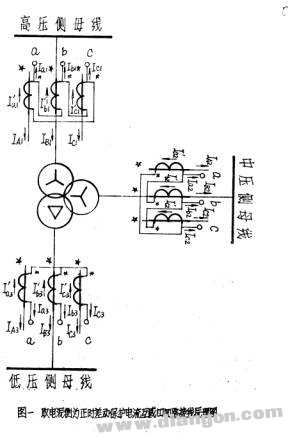
1. As can be seen from Fig. 1, the connection sequence of the high-voltage side differential protection current transformer circuit is a+→b-→b+→c-→c+→a-, and is a positive polarity outlet. For the convenience of memory, we say that the secondary side connection method of the current transformer is equivalent to the wiring of the high voltage coil of the transformer, which is equivalent to the Y/△-11 wiring group.
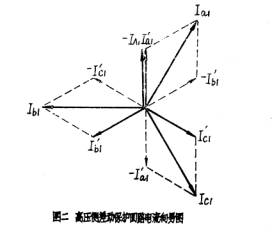
For example, we take the reverse value of I-phase current of the high-voltage side -IAl as the reference vector, and according to the current flow direction shown in Figure 1,
The current vector diagram of the high side differential protection loop as shown in Fig. 2 can be drawn.
Where: I`a1, I`b1, I`C1 are current transformer loop phase currents
Ia1, Ib1, and IC1 are current commutator circuit line currents.
2. As shown in the wiring of the differential side current protection current transformer circuit in Fig. 1, the connection sequence is a-→b+→b-→c+→c-→a+, and it is a negative polarity outlet. The above secondary current connection mode of the current transformer corresponds to the wiring of the high voltage coil of the transformer, which is equivalent to the Y/△-5 wiring.
Similarly, if we take the inverse value of the A current on the high voltage side - IA1 as the reference vector (the same below), and according to the current flow direction shown in Figure 1, we can draw the medium voltage side differential as shown in Figure 3. Protection loop current vector diagram. Comparing Fig. 3 with Fig. 2, it can be seen that the secondary side current of the medium voltage side current transformer circuit (ie, the differential circuit current, the same below) and the secondary side current of the high voltage side current transformer are exactly opposite. Towards. For the case where we assume that the primary current is the load current under normal operating conditions, the differential circuit current phase cancels, indicating that the wiring of the above differential protection current transformer four-way is completely correct.
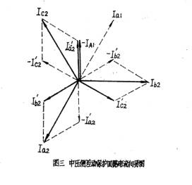
among them. I`a2, I`b2, I`c2 are the phase currents of the medium voltage side current transformer loop;
Ia2, Ib2, and Ic2 are the medium-voltage side current transformer return line currents.
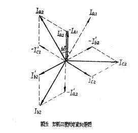
Common misconnections occur mostly on the medium voltage side. The main cause of wiring errors is that in order to obtain a reverse current (corresponding to the high voltage side), it is mistaken that when the medium voltage side current transformer is connected, the high voltage is used. The wiring method on the side is changed to the negative polarity outlet, and the wrong wiring as shown in Fig. 4 appears. It can be seen from the analysis of the above figure that the secondary side connection mode of the medium voltage side current transformer corresponds to the Y/â–³-11 wiring instead of the Y/â–³-5 wiring corresponding to the wiring of the transformer high voltage coil.
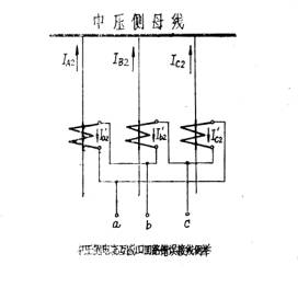
Through the vector analysis of the wiring of Figure 4, it can also be seen (as shown in Figure 5). At this time, under normal operation, the secondary line current of the medium voltage side current transformer circuit and the secondary current circuit of the high voltage side current transformer circuit The line current, the angle between the two is 60O, so the above wiring is wrong.
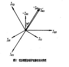
3. It can also be seen from Fig. 1 that the connection mode of the low-voltage side differential protection current transformer four-way is the star connection of the negative polarity outlet, so it corresponds to the wiring of the high-voltage coil of the transformer, which is equivalent to the Y/Y-6 wiring. Figure 6 shows the current vector diagram for the above wiring. It can be seen that under normal operating conditions, the low-side current and high-side current of the differential protection circuit are also reversed.
Where: I`a3, I`b3, I`c3 are the low-voltage side current transformer loop phase current
Ia3, Ib3, and Ic3 are low-voltage side current transformer loop line currents.
The above describes a construction method for the differential protection current transformer loop wiring. Therefore, as long as we wire according to the principle described above, the wiring of the differential protection current loop can also be ensured. On the other hand, we should point out that, due to the assumption of the primary side polarity of the current transformer, the construction method with the positive side of the main power supply is adopted, so that the wiring of the differential current circuit of the medium voltage and low voltage side differential protection is It is a normal connection method that is very common, so it is difficult for the construction personnel to remember and be prone to errors.
Here's another customary practice, which is one of the construction methods we recommend. The characteristic of this construction method is that when determining the polarity of the primary side of the current transformer, it is not positive on the main power supply side but positive on the three sides of the political bus side. In this way, the current loop wiring of the differential protection can be made simple and easy to grasp.
When the three sides are taken from the busbar side, the wiring diagram of the transformer differential protection current transformer circuit is shown in Figure 7. It should be noted that the polarity of the primary side of the current transformer is assumed only to be able to determine the polarity of the corresponding secondary side, and it is independent of how the flow of the primary side current is assumed. Therefore, the flow of the primary current we have shown in Figure 7 is still the positive direction of the load current under normal operating conditions.

For the sake of discussion, the following sections are also introduced separately on the high, medium and low sides. 1. The busbar side of the high-voltage side current transformer is positive on the primary side. This is exactly the same as the case where the power supply side (ie, the bus is the busbar side) as described in the previous "1" strip is exactly the same, so the differential protection The current transformer connection sequence and the differential protection return current vector diagram (see Figure 2) are exactly the same; they are not repeated here.
2. See Figure 7 for the wiring of the differential side current protection current transformer circuit. When the current transformer is in the primary machine, the polarity is taken as the positive side of the busbar, and the connection sequence is. a+→b→b+→c→c+→a-., and is a positive polarity outlet. Obviously, this is a common wiring method. It has the same wiring sequence as the high-voltage side differential protection current transformer circuit. It corresponds to the wiring of the high-voltage coil of the transformer and is equivalent to the Y/△-11 wiring. But let us compare the wiring diagram of the medium voltage side differential protection current transformer circuit shown in Figure 7 and Figure 1. It can be found that the actual wiring condition of the two is exactly the same, the difference is only the calibration polarity of the current mutual inductance. different. At the same time, compare the current distribution of the two. It can be seen that since we adopt the same principle when we assume the positive direction of the current, the actual flow directions of the current in the above two cases are also the same, so their differential loop current The knot of vector analysis. "
It is also completely consistent (see Figure 3)), so it will not be repeated here.
3. The polarity of the primary side of the low-voltage side current transformer is also positive for the busbar side. From the low-voltage side of the wiring schematic shown in Fig. 7, it is a star connection of the positive polarity outlet, which corresponds to The wiring of the high-voltage coil of the transformer is equivalent to the YY/12 wiring. It is also a common wiring method. 'Compared with Fig. 7 and Fig. 1, it can also be found that the actual wiring condition on the low voltage side is also the same, and the actual current flow of the current transformer loop current is also the same (the current vector analysis result is the same as Fig. 6).
From the above analysis, the final result of the two different construction practices described above is exactly the same. The vector analysis method is also the same. The only difference is that the practice of calibrating the polarity is different. The polarity name of the terminal has changed, and the wiring of different names has appeared. In this way, it is better to have a construction method than the former one. Because the latter construction method makes the name of the wiring method of the current transformer circuit appearing, it becomes a common and easy-to-memory wiring method, and therefore it is not prone to errors. So we have to recommend the latter construction method. Compared with the former construction method, this construction method has the following characteristics:
1. The three-side differential protection current transformer circuit wiring of the transformer is a normal connection sequence, which is a common typical wiring group for the wiring of the primary coil.
2. The wiring mode of the transformer high and medium voltage reverse current transformer circuit is the same.
3, are positive polarity outlets.
2.5 Small SATA SSD for PC Laptop
Compatible Devices: Compatible with desktops and laptops that accept 2.5" 7 millimeter SATA drives.
Trustworthy and Reliable:Supports TRIM command, Garbage Collection technology, RAID, and ECC (Error Checking & Correction) to provide the optimized performance and enhanced reliability.
SATA 3 2.5 inch SSD,Portable Usb C External Hard Disk,Laptop Hard Drive Enclosure,Hard Disk For Desktop Laptop,120Gb Hard Disk Memory
MICROBITS TECHNOLOGY LIMITED , https://www.hkmicrobits.com