The electronic stop sign refers to the electronic stop sign system, which includes three main parts: vehicle position information acquisition, information communication and display. At present, some large and medium-sized cities are conducting pilot bus stop signs [1-3], all of which obtain vehicle position information through GPS, communicate through GSM short message mode, and display through LCD or LED. When working, the vehicle GPS receiver obtains the vehicle position coordinate information by receiving the satellite signal, and sends it to the mobile operator's GSM short message receiving and dispatching center through short message, and the short message receiving and transmitting center transmits it to the vehicle dispatching center for processing through the special line. Obtain the information of the vehicle from the station (distance from the downstream station and the required time, etc.), and the information from the station is transmitted back to the GSM short message receiving and dispatching center by the dispatching center, and finally sent to the electronic station of the downstream station by the GSM short message receiving and dispatching center. The card is displayed through the LCD display. The existing electronic stop sign has the following two drawbacks: (1) The construction cost in the early stage is high. Although the price of the car GPS receiver is not high, if it is fully promoted and applied in the city's bus, it will need to invest huge amounts of money; (2) the high operating costs in the later period. The high operating cost is mainly caused by GSM short message communication. In order to improve the positioning accuracy, the vehicle needs to perform positioning (receiving a satellite signal) every few seconds to several tens of seconds, and send a short message to the GSM transceiver center. The GSM transceiver center must send the information of each station's station to the electronic station card, that is, each time the vehicle performs a positioning, it needs to send two short messages (one from the vehicle to the GSM center and the other from the GSM center to the downstream). Station electronic stop sign), so the number of short messages is very large. Although the price per short message is not high, the communication cost caused by such a huge amount of short messages is unaffordable for the bus company. If it is passed on to consumers, consumers will not accept it. Therefore, such electronic stop signs are currently only piloted on certain lines, and it is difficult to promote the application. This paper proposes a new electronic station solution, which reduces the pre-construction cost by replacing the car GPS receiver with the use of in-vehicle electronic tags (RFID), and reduces the communication cost by using the power line to transmit the vehicle location information instead of the GSM short message. .
1 system compositionThe block diagram of the electronic station card system described in this paper is shown in Figure 1. It consists mainly of the station device at the station, the electronic tag installed or attached to the car, the power line and the dispatch center.

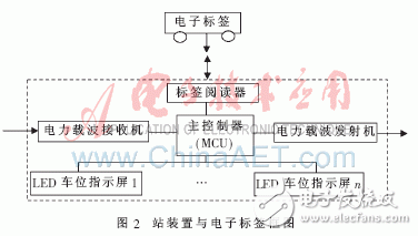
The station device is the core part of the electronic station card system. As shown in Figure 2, it is mainly composed of a tag reader, a power carrier transmitter, a power carrier receiver, a main controller (MCU) and an LED parking space indication screen. The electronic tag is attached/posted on the bus, and the vehicle code information (the coded representation of the certain car of a certain road) is pre-stored in the electronic tag.

The tag reader is used to read the vehicle code information carried by the on-site vehicle electronic tag. The power carrier transmitter will couple the digital signal to the next station for carrier modulation and then couple it into the power line for transmission. The power carrier receiver demodulates the received modulated signal (from the upstream station) and restores it to a digital signal.
The main controller (MCU) mainly performs processing, storage, transmission and control of vehicle code information. The main controller obtains the coded information of the station vehicle from the tag reader, and obtains its number after processing (ie, a certain road of a certain road), on the one hand, through the LED parking space indication screen of the station, and adds the station. The station code is sent to the next station by the transmitter. The main controller also obtains the station code and the car code information sent from the upstream station from the power carrier receiver, so that it is known that a certain car of a certain road arrives at a certain station, except for display on the display of the station, The power carrier transmitter is passed to the next station.
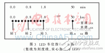
The LED parking space indication screen is as shown in FIG. 3, and includes an LED light group and a screen substrate. The station name, the tick mark, the number of kilometers, and the number of minutes are printed on the screen substrate. The station name is aligned with a certain tick mark, and the number of kilometers from the departure station and the travel time of the bus are marked above the tick mark. The length of the bus line, the station location, and the time required for the vehicle to operate are fixed (normal), so the number of kilometers from each station along the line and the required travel time can be marked on the scale line. Install one LED on each scale line and set several LEDs between the two scale lines. When the bus arrives at a station, the LED on the scale line corresponding to the station is illuminated, and when leaving the station, the LED on the corresponding scale line is turned off, and the tick mark of the station and the next nearest station are successively illuminated according to the historical driving time. Corresponding to the LED between the tick marks.

Through the LED parking space indicator screen, passengers can always know the location of the bus along the line, the distance from the station and the time to arrive at the station. If you can't arrive within the predetermined time, you must have blocked the car, and you can know the position of the car. From the received car code and station code information, the dispatch center can know where a certain car is currently located at a station or between two stations, where should the next time arrive, and if it cannot be reached within the expected time, It is known that the car has been blocked and scheduled according to the situation. This information can be visually displayed via the LED parking space indicator or PC.
Optoelectronic Information Series
Photoelectric information series laboratory related equipment
Optoelectronic Information Product,Optical Bench Experiments Physics,Optical Devices Physics,Optical Physics Properties
Yuheng Optics Co., Ltd.(Changchun) , https://www.yhenoptics.com