On today's system boards, there are more and more voltage rails and power supplies. For advanced power supply designs, size, efficiency, thermal performance, and transient performance are critical, so designing a custom built-in power supply design for a specific application, rather than using commercial power bricks, is more efficient. There will also be better cost-effectiveness. Designing and optimizing switch-mode power supplies has become more common for system engineers and has become a necessary task. Unfortunately, such tasks often take a lot of time and are technically challenging.
To simplify this design task and improve design quality and productivity, Linear Technology's power application experts have developed the LTpowerCAD program for power supply design and optimization tools. This article describes how to perform a “paper design†of the key parameters of a switch mode power supply through a few simple steps and get good design results.
“Paper design†can be very difficult and time consuming
To design and optimize a built-in power supply, the traditional "paper design" approach can be very difficult and time consuming. After defining the power performance specifications, engineers first need to choose a converter topology, such as a buck converter for buck applications or a boost converter for boost applications. Second, engineers need to choose a power management IC, select it based on past experience, or search for available tools online. The engineer then needs to calculate the value of the power component based on his or her knowledge or the formula provided by the manufacturer in the datasheet. The next step is to select power components such as inductors, capacitors, and MOSFETs from thousands of devices. The next step is to estimate power efficiency and power consumption while ensuring that the thermal burden of the components is acceptable. Looping compensation design is another challenging task, because completing such tasks requires complex circuit models and parameter values ​​not provided by the IC datasheet. Finally, draw the schematic and send the prototype PCB board to production. Now, it's time for the engineer to power up the board. At this step, the engineer must make sure there are no oscillating outputs or overheating problems. For an inexperienced power designer, the above design process is challenging. Even experienced power designers, traditional "paper design" methods and experimental and troubleshooting methods are difficult, and take a lot of time, the results are not accurate enough, often do not get the best results. It can take hours, days or even longer.
LTpowerCAD design tools simplify design tasks
To help users save time, reduce workload and achieve high-quality design solutions, Linear Technology's power application experts have developed LTpowerCAD design tools. This design tool provides a systematic and easy way to design key power parameters in five easy steps: (1) input power specification parameters, select a design; (2) help with automatic prompts Optimize power stage parameters; (3) optimize power efficiency and power consumption; (4) design loop compensation and optimize load transients; and (5) generate summary reports with BOM and PCB size estimates. Figure 1 shows the design flow for using the LTpowerCAD design tool.
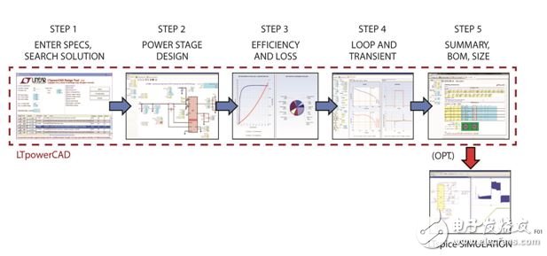
Figure 1: Using LTpowerCAD design tools to design power supplies in 5 easy steps
There are many existing design examples, including Linear Technology's demonstration boards and datasheet circuits in the LTpowerCAD design library. Users can also save their designs with LTpowerCAD to build their own design library. Engineers can use this type of design to quickly find a starting point for future power supply designs. In addition, can LTpowerCAD design also be used as LTspice? Simulate circuit output to check time domain power waveform and transient performance.
With these powerful tools, system engineers can complete a high-quality power circuit design in minutes instead of hours or days and get good results. The time to produce the first prototype board is greatly reduced.
LTpowerCAD design steps and examples
Below we use a LTpowerCAD design example to detail these design steps. For example, an engineer needs to design a built-in power supply with an input range of 10.8V to 13.2V (12V ±10%), an output of 1.0V, and a current of up to 20A. This is a typical synchronous buck converter.
Step 1 â” Search for power product design
The first step is to search for critical power ICs or micromodules, which are at the heart of the design. You can rely on past experience to choose an IC or micromodule (μModule?), or you can go to the LTpowerCAD design search page to find it. As shown in Figure 2, on the LTpowerCAD search page, the user can enter power supply specifications, select optional features, and then click the "Search" softkey. After that, select the desired device from the list provided by the program.
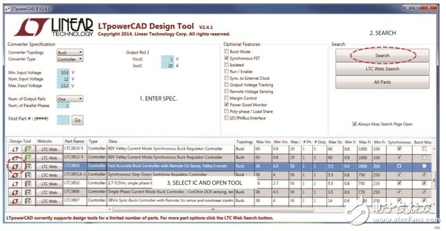
Figure 2: Design Step 1: Search for Power Supply Design
In Figure 2, the leftmost part of the list of IC design options provided by the program is the red "LT" symbol or the green "Excel" symbol. The red "LT" symbol means that the LTpowerCAD design tool is available for the device. The green "Excel" symbol means that design tools based on Microsoft Excel spreadsheets are available. If both symbols are gray, it means that the device does not have a suitable design tool.
In this example, the LTC3833 current mode step-down controller was selected for the 12VIN to 1V/20A output. Click on the red "LT" symbol to open its design tool.
Step 2 â” Power Level Design
The second step is to design and select power stage components such as power inductors, input and output capacitors, current sense components, and power MOSFETs. When designing a power supply, the user usually needs to start with the switching frequency fSW, then select the power inductor, and then select the input and output capacitors. The power MOSFET can be selected/optimized in the third step.
As shown in Figure 3, after the design tool opens, the main schematic page is displayed, alongside the key components, which are the design parameter values. On this page, the design parameter values ​​are in the cell (text box) and have two different background colors. Yellow indicates that the value in the cell is either from the design specification or is calculated/recommended by the LTpowerCAD tool. Users cannot directly edit these values. Blue indicates that the value in the cell is the user's design choice. Users can access and edit these values ​​directly.
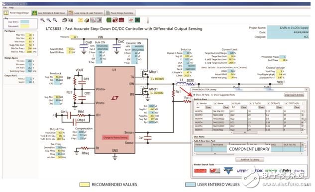
Figure 3: Design Step 2: Power Level Design Page, providing schematic and key parameter values
For critical circuit parameters such as inductor ripple current, the program provides built-in limits for each device. As shown in Figure 4, if the user-designed value exceeds this limit, the program automatically issues an alert, displaying a weaker "soft" alert in orange cell color, or a stronger "hard" in red cell color. Alerts to alert and guide the user to check the value and adjust the design. The built-in limit/alarm threshold is the recommended value set by the application specialist for the relevant product. It is important to mention that because this is an analog design, sometimes even with an alarm, the design is acceptable as long as the user knows them and is convinced with the chosen design value.
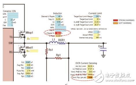
Figure 4: Automatically issued alerts guide the user in selecting the appropriate design value
On this LTpowerCAD schematic page, all power components (such as inductors, capacitors, and FETs) can be selected from the built-in library with the click of a mouse. As of this writing, the library already includes more than 5,000 components from many popular vendors, and often adds more components. Users can also enter key parameters for a new component and build their own component library on the local PC.
In this 12VIN to 1V/20A step-down power supply example, the switching frequency is set to 500kHz. Therefore, to achieve 40% peak-to-peak inductor current ripple on DC IO(max), the calculated inductor value is 0.23μH. A 0.22μH/1.1mΩ inductor is selected from the inductor bank. In this example, the DC resistance (DCR) of the inductor winding is used for current sensing. The value of the current sense network should be checked to properly set the current sense signal and current limit. If the AC current sense signal is too weak, the program will sound an alarm because it may cause a signal-to-noise ratio problem, or if the current limit value is lower than the target value, the program will also sound an alarm. When selecting an input capacitor, the RMS current rating should be met with the lowest conduction loss. Minimize output voltage ripple and transient overshoot/undershoot when selecting an output capacitor. These capacitors will be finalized at a later stage of loop compensation and load transient design. The power MOSFET will be selected in the next step for high efficiency, estimated power consumption, and optimization.
What is a wireless AC controller? What does it do?
Wireless AC controller is a kind of network device, such as the AC100/150 of Fengrunda, which can be used to centrally control and manage wireless aps. It is the core of a wireless network and is responsible for managing all wireless aps in the wireless network. AP management includes: delivering configuration, modifying related configuration parameters, RF intelligent management, and access security control.
Why use a wireless controller, and what exactly does it do?
In fact, the role of the wireless controller is to play a gateway function between the WLAN and the Internet (on the router), and the data from different access points are aggregated and accessed to the Internet. The role of an access point (AP) is to complete wireless access, and it can control user access through network flags.
The role of wireless controllers
1, Flexible networking mode and excellent scalability
The AP does not need to be directly connected to the AC, so that the AP can be deployed in any place that needs to be covered through the network, such as you deploy an AP in each employee's home, and then connect to the wireless controller inside the enterprise through the VPN, you can expand the wireless network of the enterprise to the family of each enterprise member.
2, intelligent RF management functions, automatic deployment and fault recovery
Through the dedicated RF management module, we can initially estimate the AP deployment according to the user's architectural design drawing, and can calculate the average bandwidth of the wireless terminal, the coverage between AP and AP in the actual debugging process.
3. Centralized network management
All the configuration of the wireless network can be completed by configuring the wireless controller. For example, enable, manage, and maintain all AP devices and mobile terminals, including all functions such as radio wave spectrum, wireless security, access authentication, mobile roaming, and access users.
4, powerful roaming function support
The wireless controller uses AP as the boundary combined with fast RF management system, which greatly reduces the connection time between wireless client and AP, and thus realizes the function of fast roaming.
5. Load balancing
AP and wireless controller systems can distribute wireless users or terminals to nearby aps within the coverage area of an AP, ensuring the number of each wireless terminal or the sum of AP bandwidth transmission or the upper limit of each wireless terminal bandwidth.
6, wireless terminal positioning, rapid fault location and intrusion detection
Wireless controllers can track and locate the location of wireless terminals, such as wirelessly connected computers, PDAs and Wi-Fi mobile phones.
7, powerful access and security policy control
At present, the wireless system supports authentication of 802.1, WEB authentication, MAC, SSID, VPN, etc., and supports various encryption modes such as WEP, WPA, WPA-PSK, WPA2, etc., and all configurations can be configured globally through the wireless controller.
8, Qos support
AP and wireless switching systems can limit the maximum bandwidth of a user's wireless connection within each user's privileges. For different IP services, the system can also define different QoS queues through the wireless switch module. For example, for wireless voice applications, SIP and RTP protocols can be set in the high queue, while common applications such as http and ftp can be set in the low queue.
The wireless controller AC is more advanced than the AP, plays the role of manager in the wireless network, and the wireless controller AC also acts as a client to complete a series of functions in the wired network (such as authentication, authentication, etc.). However, wireless controller AC is not a WLAN device specified in the 802.11 protocol family, but as a supplement to the protocol in specific applications, and its price far exceeds that of ordinary access point (AP) devices.
In small-scale wireless networks that use only a few aps, it is not economical to use expensive wireless controller AC equipment. However, if the number of wireless aps is large, more than 20 can be used AC controller.
Ac Controller,Gigabit Wlan Controller,Enterprise Ac Gateway,Wireless Ap Controller
Shenzhen MovingComm Technology Co., Ltd. , https://www.movingcommiot.com