Zhang Hanyu said that the car you choose, let others see what you look like, your experience, and even your future. For engineers in the automotive electronics industry, the same is true for choosing an oscilloscope. Today, how can I use the oscilloscope to "invade" the interior of the car as much as possible?
This article refers to the address: http://
Today, cars have become the most important means of transportation in human life. Looking at the cars on the street, the major manufacturers have their own tricks. Apply the most popular Internet of Things to the car, which is the “Internet of Vehiclesâ€. For example, the domestic Internet giant Alibaba joined hands with the automobile to cover the concept of the Internet of Everything.
For the time being, most manufacturers' "vehicle networking" is based on the traditional OBD interface as an access point for acquiring on-board status. It is not possible to get all the communication data of the car. So what is the real test demand in the automotive electronics industry, or what do we really “invade†the interior of the car?
First, from the car bus
In the communication process of the car, the most familiar one should be the CAN bus. In addition to the CAN bus, there are the following. Next, let's look at it one by one.
1. CAN (Controller Area Network): The CAN controller area network has become an international standard with hundreds of chip types. With high reliability and good error detection capabilities, it is widely used in automotive and embedded applications.
The physical layer and data link layer of the CAN protocol structure have been implemented by hardware, and are currently standardized, with ready-made components (CAN controllers and transceivers). Therefore, the CAN controller and transceiver are added to the MCU, and the corresponding driver is implemented by the software to realize the CAN communication function.
2. LIN (Local Interconnect Network) bus: It is easy to implement, low cost, and can be applied to occasions where real-time performance is not high. Controls such as lights, doors, seats and wipers are the areas of application. As an effective compensation for CAN networks, the biggest advantage is the low cost. The first is mainly because it takes the UART data format, so there is no need for a separate controller, it can be implemented in software on the UART. The use of the LIN bus in a car is shown in Figure 1.
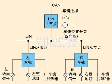
Figure 1 LIN bus in the car
3. FlexRay: is a newer communication communication protocol that spreads faster than CAN and LIN and has higher reliability, but it is also more expensive. Disadvantages of FlexRay: Its electrical characteristics result in limited network length. FlexRay's actual products are only used in BMW, Audi, and Mercedes. At the end of 2009, the alliance of FlexRay was dissolved. The application of the protocol is far less extensive than the first two.
CAN FD (CAN with Flexible Data rate): In the automotive field, as the demand for data transmission bandwidth increases, the traditional CAN bus is difficult to meet this increased demand due to bandwidth limitations. In addition, in order to reduce the bandwidth gap between CAN network (max. 1MBit/s) and FlexRay (max.10MBit/s) networks, BOSCH has introduced CAN FD.
CAN FD inherits the main features of the CAN bus. At the same time, the CAN FD bus compensates for the CAN bus bandwidth and data field length. The CAN FD bus differs from the CAN bus mainly in variable speed and new data field length. Its data frame frame format is shown in Figure 2.
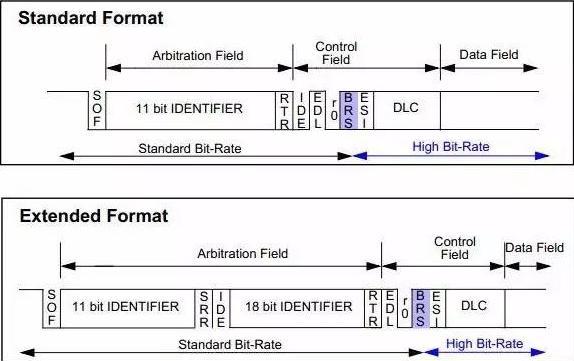
Figure 2 CAN FD data frame frame format
5. SENT (Single Edge Nibble Transmission): A point-to-point, one-way transmission scheme used to transmit high-definition sensor data between sensors and electronic control units (ECUs) in automobiles.
SENT (SAE J2716) is a new interface standard for automotive sensors that offers excellent EMC characteristics compared to analog outputs and PWM outputs, saves wiring harnesses, saves cost-effective solutions for pin headers, and transmits fault codes to enable sensor systems Has a strong ability to diagnose faults. SENT will widely replace CAN and LIN in local systems.
For the above communication protocol, our commonly used test tool is an oscilloscope. So what kind of oscilloscope do you need to do an accurate test?
Second, the automotive electronics industry requirements for oscilloscope parameters and functions
1) Protocol decoding: compatible with all major automotive communication protocols, CAN, LIN, FlexRay, SENT, CANFD;
2) Large memory depth: not simply decoding a frame of waveform, but completely monitoring the entire communication process;
3) Parameter measurement: It is necessary to support the measurement of various parameters such as baud rate and bus load rate.
Third, why did you choose ZDS4054Plus?
1) Free standardization of more than 30 kinds of protocol decoding: including CAN, LIN, FlexRay, SENT, CANFD commonly used in the automotive electronics industry. Compared with other oscilloscopes in the industry, the ZDS4054Plus can support 70s CAN waveform decoding based on 512M memory depth. The large memory can monitor the entire communication process, as shown in Figure 3 and Figure 4. Show.
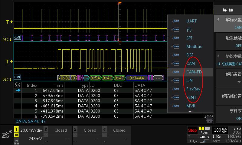
Figure 3 Free standardization of more than 30 kinds of protocol decoding
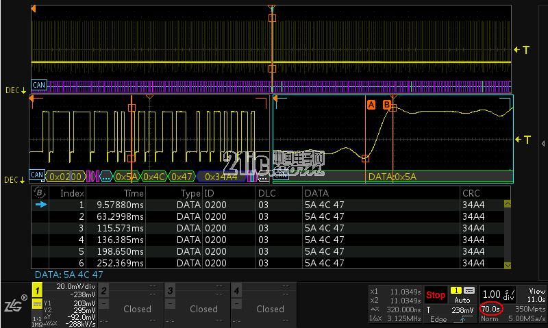
Figure 4 70s CAN waveform decoding
2) Support dual ZOOM mode: Dual ZOOM function, as long as it is used once, will never forget. Different scaling factors can be set for each of the two windows, so that two different time axis range zoom waveforms can be displayed simultaneously. With the convenient operation of the touch screen and large knob, the waveform of each window can be easily controlled. At the same time, based on the dual ZOOM positioning to the problem frame, to observe the rising and falling edges of the problem frame. As shown in Figure 5.
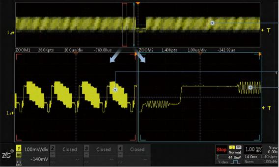
Figure 5 Dual ZOOM mode
3) Event table with full memory depth and full protocol decoding: All waveforms under 512M memory depth can be decoded and displayed in the event table. The event table can observe the time, frame type, IDField, data and other information of a specific frame waveform, which greatly facilitates our analysis of the waveform. Figure 6 shows the decoding of the LIN protocol.
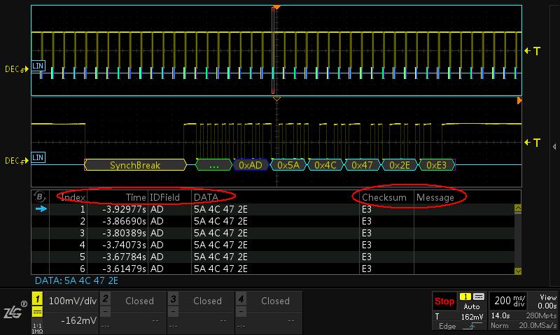
Figure 6 decoding of the LIN protocol
4) Support CAN bus baud rate and load rate measurement: ZDS4054 plus supports 51 kinds of parameter measurement, 24 kinds of same screen display, as shown in Figure 7. The only direct support for CAN bus baud rate, load rate direct measurement, all measurements are through the FPGA full hardware acceleration, even if 512M waveform data measurement less than 1s. Figure 8 shows the CAN bus baud rate, average and instantaneous load rate measurements.
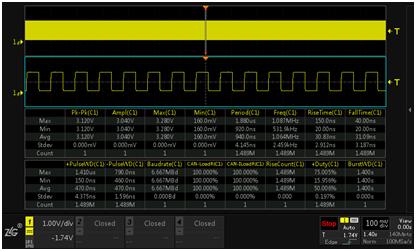
Figure 7 24 parameters displayed on the same screen
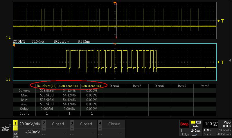
Figure 8 CAN bus baud rate, load rate measurement
5) Support frequency/rising edge slope measurement: measure the rising and falling edge slope of the waveform, positive and negative pulse width, etc., as shown in Figure 9.
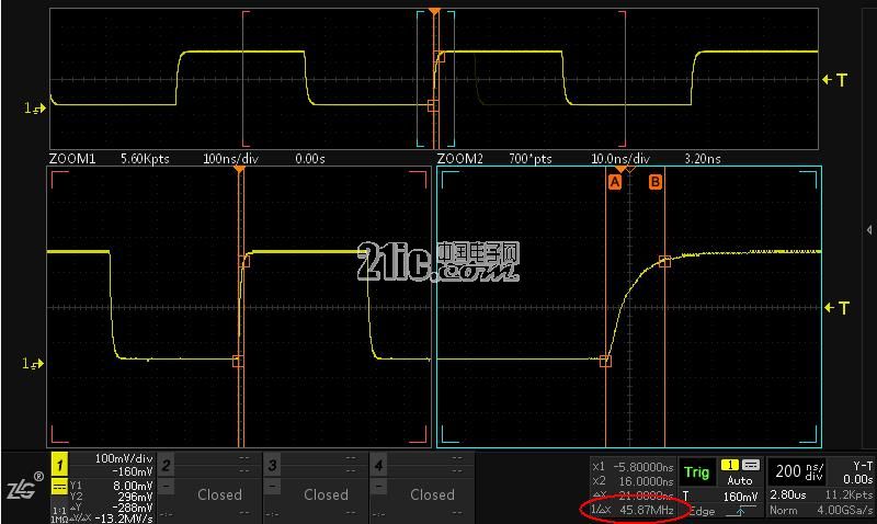
Figure 9 Measurement of the rising slope of the waveform
In addition to the above features, you may also need the following features:
lFIR hardware real-time filtering: Each channel has a built-in filter from 50Hz to 200MHz, which is suitable for filtering out unwanted signals and observing specific bandwidth.
l4M FFT function: the sampling rate is 4GSa/s, the frequency resolution can be accurate to 250Hz at 1G sampling rate, and the source of interference noise in the circuit can be accurately analyzed;
l Waveform comprehensive analysis software: 512M waveform big data is exported to the upper computer through Ethernet for further offline analysis.
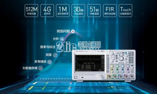
Figure 10 data mining oscilloscope
20L Agriculture Drone,Agriculture Sprayer Drone,Professional Sprayer Drone,Agriculture Sprayer
Xuzhou Jitian Intelligent Equipment Co. Ltd , https://www.jitianintelligent.com