The GSM communication network has become very popular, and it has basically achieved seamless coverage in China. The GSM wireless network system operates reliably and its encryption technology is very mature. The GSM network dedicated module TC35I, Bluetooth wireless data communication chip nRF401 and microprocessor were used for comprehensive development, and the preliminary design and experiment of the intelligent toll collection system with no toll station and no parking verification was completed.
This article refers to the address: http://
1 System working principle
The system is mainly composed of two parts: one is the in-vehicle system, its structural block diagram is shown in Figure 1; the second is the fixed base station and the egress base station system at the entrance of the expressway, its structural block diagram is shown in Figure 2.
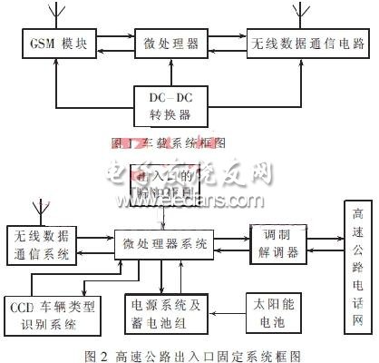
1.1 Vehicle system
The vehicle system consists of a GSM network dedicated module TC35I with SMS function, a single-chip control system and a wireless data communication circuit based on Bluetooth technology. The microprocessor is connected to the GSM module TC35I through the circuit at a rate of 19.2 kb/s, and calls the international mobile identification code and mobile phone number of the mobile phone, and automatically fills in the identification information. The wireless data communication circuit has a communication distance of more than 100 meters. When the vehicle passes through the highway entrance and exit at a speed of 40km/h, it ensures that the authentication and charging communication are completed within 1~3 seconds.
The MCU control system enters the standby state after power-on and completes initialization, and the wireless data communication is in the receiving state. After receiving the instruction from the base station, the received information is analyzed. If it is a highway entrance, the entry information and the charge number are stored in the internal EEPROM, and the encrypted identification information is sent; if it is an exit, the entry related information and the identification information are sent together to the exit base station, and the exit base station receives The information obtained is verified one by one, and the verification result and charging information are returned. Finally, the charging text message sent by the toll collection center entrusted by the expressway management system is received through the GSM network. After the system completes the data exchange, the wireless data communication circuit enters a short sleep state for five minutes, avoiding repeated reception of portal information or affecting wireless communication of subsequent vehicles.
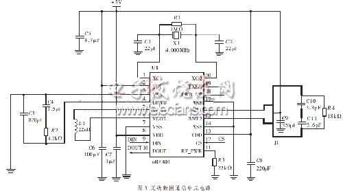
1.2 Highway entrance and exit fixing system
The fixed system is divided into an egress base station and an ingress base station, and the physical structure is basically the same, and the functions are different. In the entrance part, the vehicle model of the vehicle that is about to enter the expressway is first verified by the CCD to determine the charging price; and then the wireless data communication system issues an instruction to verify whether the vehicle has an automatic payment system. After receiving the response from the in-vehicle system and determining that the vehicle has the automatic payment function, the vehicle characteristic information, the "identity" verification information, and the automatic charging number of the vehicle are notified to the respective outbound ports through the modem and the fixed telephone network. System; simultaneously transmitted to the in-vehicle system via wireless data communication for verification at the outbound. After the vehicle is released, it is verified through the telephone network whether the vehicle has the ability to pay. If a car does not have the ability to pay automatically or owe money, the wireless system at each intersection will track the whereabouts of the car, and promptly feed back information to each duty station, and force the charges through the on-duty personnel.
Each of the export fixed base station systems first detects that a car arrives through the CCD, and when the wireless communication is within the valid range, starts the wireless communication system, receives the entry information, the toll number, the vehicle type and the identification information of the vehicle, and the entrance system. The information transmitted through the wired network is compared. If everything is normal, the threshold is opened, the pass is passed, the charging center is notified, and the charging text message is sent. The paid SMS content includes information such as date, model, entrance and time, exit and time, and total distance. On the contrary, it must be charged by the duty officer and released by manual operation.
2 main component selection and interface circuit design
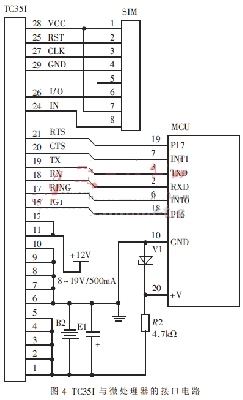
2.1 Wireless data communication circuit
The wireless data communication circuit is mainly responsible for performing close-range wireless data exchange tasks between the motor vehicle and the fixed base station system. It consists of the core chip nRF401 and its accessory components. nRF401 is a dual-channel, high-performance, low-power dedicated wireless communication chip with an operating frequency of 433.93/434.33MHz, a working voltage of 3.3V, and a maximum communication rate of 20kbps. It can be directly connected to the serial port of the MCU for asynchronous communication. Data is sent and received without encoding the data. The data input terminal DIN is connected to the TXD terminal of the single chip microcomputer, and the data output DOUT terminal is connected to the RXD terminal of the single chip microcomputer. In this circuit, the communication rate is designed to be 19.2 kbps. The circuit principle is shown in Figure 3.
2.2 GSM communication module
The GSM communication module uses SIEMENS' TC35I. TC35I is a special module designed by SIEMENS for GSM communication. It has voice, data, fax and point-to-point SMS functions. It works in EGSM 900 and GSM 1800 frequency bands, weighs only 10g, and can work normally in the range of 3.5~4.8V. The main instructions defined by AT Commands Interface Version 8.5 are well executed, and there are more than 20 extension instructions.
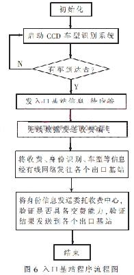
The TC35I interface consists of a 40-core cable. The 1 to 5 pins are connected to the "+" end of the battery. The 6 to 10 pins are connected to the "-" end of the battery. The 11 to 12 pins are the DC power input terminals. The input can be 8 to 20V/500mA. DC power, there is an automatic charging control circuit inside. The 15-pin IGT is the module start-up control, and the 31-pin EMERGOFF is the shutdown control. Both are active low and can also be turned on and off by commands. The 17-pin is the ringing output, the 18-pin RX is the serial data output, the 19-pin TX is the serial data input, the 32-pin is the working status indicator output, and the 24-29 pin is connected to the SIM card. The interface circuit with the microprocessor is shown in Figure 4. The communication rate is 19.2 kbps.
All instructions for the TC35I can be downloaded from the SIEMENS website.
2.3 CPU control circuit
The vehicle user mobile payment system consists of a low-cost AT89C4051 single-chip microcomputer with a working power supply of 3.3V. The base station is equipped with a high-speed, high-performance 77E58-40 single-chip microcomputer to complete wireless data communication and identity verification functions. The CCD model identification is completed by another independent processing unit.
3 software implementation
The microprocessor part of the software is written in C51, all modular structure. The vehicle part mainly completes the identification and payment functions, and exchanges information with the base station. The main program block diagram is shown in Figure 5; the main block diagram of the entrance base station is shown in Figure 6; the egress base station is similar to the entrance and is not listed.

The highway automatic toll collection system using GSM has low operating cost, reliable and convenient information encryption system, and has broad application prospects and market. But to form a complete charging system, there are still many areas that need improvement.
3.2V Battery Cells,Prismatic Phosphate Lithium Batteries,3.2V 202Ah,3.2v lifepo4 battery,3.2V LifePO4 Lithium Battery Pack
Jiangsu Zhitai New Energy Technology Co.,Ltd , https://www.zhitaibattery.com