Toyota is quite persistent with hybrids, especially non-plug-in hybrids. Therefore, even in the development of pure electric power systems, this "hybrid" thinking is also in the shadow.
This article refers to the address: http://
As in the previous article, "The fuel efficiency improvement of 30%, the "special pet" hybrid Toyota watch is wrong?", as mentioned in the transition to the pure electric vehicle, the internal combustion engine will still play an important role. Therefore, even Toyota, which is a mixed injection, has not given up on the research of the engine. How to make the internal combustion engine continue to glow in the pure electric vehicle business is also one of the research directions of engineers.
It is under this guiding ideology that Toyota's Central Research Institute has developed a new type of generator with a power of 10 kW. Although this linear generator is a generator, it is transformed from the structure of the internal combustion engine. There is an unclear name - Free Piston Engine Linear Generator (hereinafter referred to as FPEG), free piston engine linear power generation. machine. The biggest difference from the traditional engine is the addition of a power generator to the cylinder.
Toyota expects a pair of 10 kW generators to allow a B/C class pure electric vehicle to cruise at speeds of up to 120 km/h. It should be known that for pure electric vehicles, the driving speed is always limited by the cruising range. Although many electric vehicles can have a top speed of more than 150 km/h, this number will be greatly reduced in order to get the maximum cruising range. So how does Toyota do it?
In fact, the principle of this new invention is quite simple, and it is also the physics knowledge in high school - electromagnetic induction.
We know that in a conventional internal combustion engine, the crank-link mechanism allows the piston to reciprocate in the cylinder, converting the chemical energy of fuel combustion into mechanical energy for output. In FPEG, a magnet is added to the outside of the piston. The reciprocating motion of the piston cuts the magnetic induction line generated by the magnet, and the external induction coil generates electromagnetic induction, which converts the kinetic energy of the piston movement into electric energy.
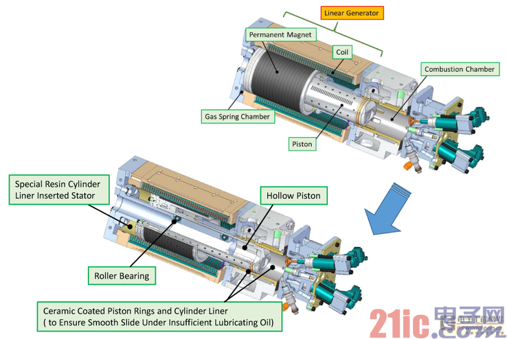
At present, Toyota Academia Sinica has only produced a prototype for experiments. The prototype was modified on a two-stroke cylinder consisting of a combustion chamber, a linear generator and a gas spring chamber.

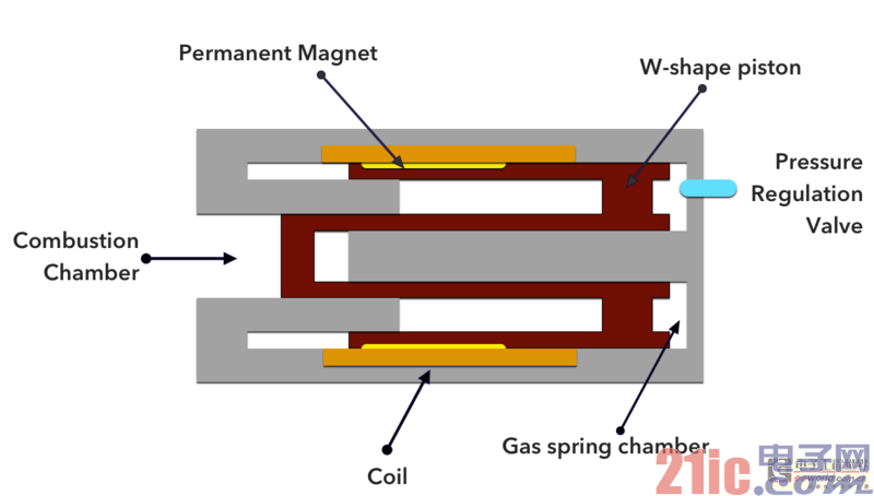
Cylinder structure profile
In conventional engines, the key structure for the reciprocating motion of the piston to circulate is the crank linkage. In FPEG, since the mechanical energy is not directly output, and the magnet is added to the cylinder, the crank link structure is directly canceled. The magnet is attached to the piston, and in the original cylinder block, an induction coil and a stator embedded in the cylinder liner are added, and the magnet, the induction coil and the stator together form a linear generator. A linear engine can be thought of as a permanent magnet motor that can be used as both a motor and a generator.
The most critical structure in FPEG is a hollow piston. The diameters of the two ends of the piston are different. Among them, the small diameter end and the cylinder block form a combustion chamber, and the large diameter one and the cylinder together form a gas spring chamber. As can be seen from the above sectional view, the cross-sectional shape of the piston is a W, and Toyota also refers to this type of piston as a W-shaped piston.
After the crank-link structure is cancelled, the gas expansion of the combustion chamber can only make the piston move in one direction, that is, it can only "go" but not "re-". In FPEG, the gas spring chamber is the end that ensures that the piston can return to the combustion chamber for the next cycle. Gas combustion pushes the piston to work while compressing the gas in the gas spring chamber, which is equivalent to storing a part of the kinetic energy of the piston in the gas spring chamber. When the compression reaches a certain level, the piston is pushed back to move. There is a pressure regulating valve in the air spring chamber, which can adjust the pressure according to different working conditions of the engine.
In addition, the basic structure of FPEG is basically the same as that of a single-cylinder two-stroke engine. At one end of the combustion chamber are provided a fuel injector, a spark plug (the prototype uses gasoline as fuel) and an exhaust valve, and the mixture enters the combustion chamber from the scavenging hole of the cylinder liner.

FPEG simulation profile
The design of the W-shaped piston is the key to FPEG. In the base of the cylinder, there is a fixed cylindrical column. The hollow piston is attached to this fixed pillar for reciprocating motion, and the inside of the fixed pillar is designed with a cooling oil pipe. In order to ensure that the piston can normally reciprocate under insufficient lubrication conditions, a ceramic coating is used on both the piston and the cylinder liner to reduce friction. The position of the magnet attached to the piston is set at the end away from the combustion chamber to avoid degaussing due to the influence of high temperature.
Compared with the traditional engine, the mechanical loss of the engine is greatly reduced after the crank-link mechanism is not used. The gas spring chamber that pushes the piston to reciprocate is also relying on gas compression to do work, but the larger the cross-sectional area, the problem after the gas is compressed. The lower, the less the heat loss in the whole process. In power generation, since the gap between the magnet and the coil is fixed, power generation efficiency can be ensured. In the simulation experiment, the thermal efficiency of both the gasoline engine and the diesel engine was improved, and the diesel engine efficiency under 10 kW reached 42%.
Of course, everything has its advantages and disadvantages.
Although the crank-link mechanism is eliminated, the structure of the engine is greatly simplified and the thermal efficiency is improved, but the problem that comes with it is that the determination of the position of the piston becomes a problem because it cannot be determined by the corner of the crank. However, the position of the piston is a crucial factor. The time for fuel injection, ignition, opening and closing of the exhaust valve is determined by it. In FPEG, the movement of the piston cuts the magnetic induction line to generate an electromagnetic reaction to generate electricity. The location is even more important.
In order to know the specific position of the piston, the institute designed a number of grooves on the piston and installed a gap sensor on the inner surface of the cylinder. The depth of the groove on the piston is different. When the piston is running at different positions, the gap with the inner surface of the cylinder is different. The gap sensor determines the position of the piston through the gap.
Another problem with no crank linkage is that the top dead center and bottom dead center of the piston are no longer fixed. In FPEG, the piston reciprocates against a fixed strut in the cylinder. Although the length of the strut determines the range of motion of the piston, the upper and lower dead centers are not fixed within this range of motion. The top dead center depends on the ignition time. When the ignition gas expands, the combustion gas expands and the piston starts to descend. The bottom dead center depends on the pressure of the gas spring chamber. When the pressure of the gas spring chamber reaches a certain value, the piston is pushed upward. In addition, the upper and lower dead points are not fixed, and the compression ratio of the cylinder is no longer a fixed value.
In order to ensure the stability of the combustion process, the position of the upper and lower dead points must be precisely controlled. Therefore, although the mechanical structure is simplified, the requirements for the engine control system are higher, and the setting of the control system is more complicated. Moreover, the requirements for the control system do not stop there. One of the reasons why the two-stroke engine is not popular is the coincidence of the exhaust and the intake process. During the ventilation process, it is easy to have the unburned mixture with the exhaust gas, which causes loss, so in FPEG, The opening and closing times of the exhaust valves also need to be precisely controlled.
Of course, the increase in controllable factors also has the advantage that it can be adjusted at any time according to the operational needs to ensure that the engine is always running under high efficiency conditions.
So far, FPEG is still in the experimental stage. The prototype of FPEG was stable in the laboratory for 4 hours, and no problems of cooling or insufficient lubrication were found. However, if mass production is required, engineers still have a lot of work to do. In addition to the control system, further research is needed on the reliability, stability, life, and even the output power and conversion efficiency of the system.
Solar Double-ended Brush,Solar Panel Cleaning System Tool,Solar Panel Cleaning Brush
GuangZhou HanFong New Energy Technology Co. , Ltd. , https://www.hfsolarenergy.com